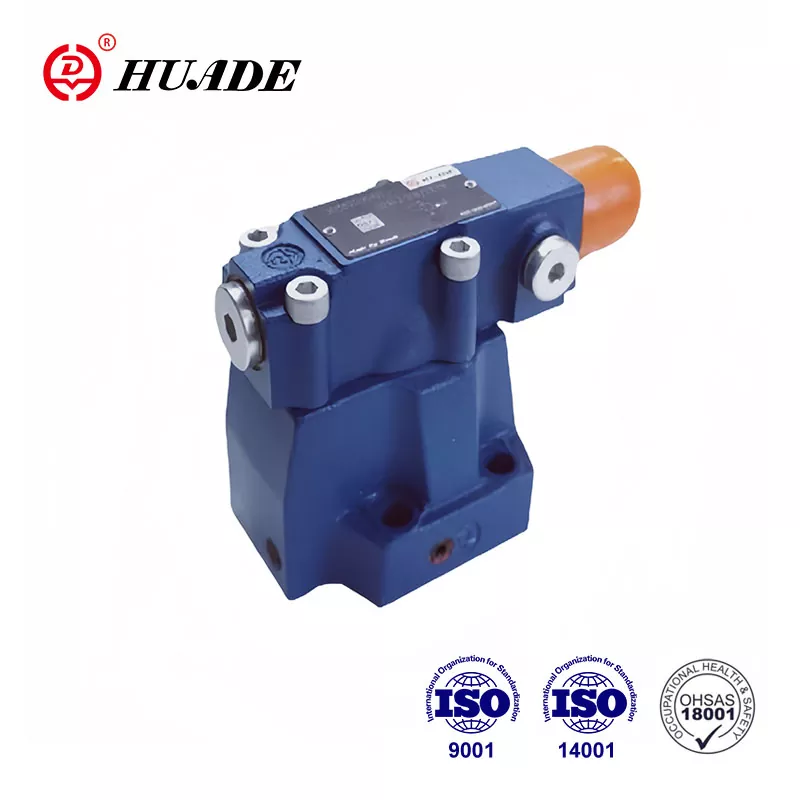
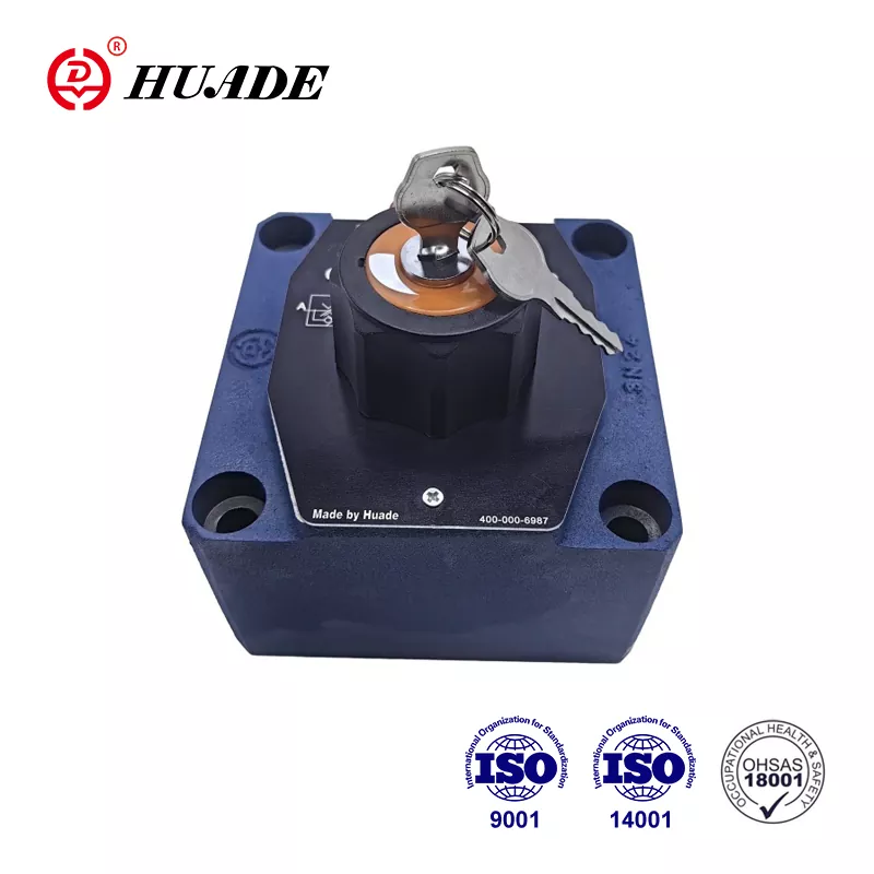
Hydraulic directional control valves serve as the command center of fluid power systems, determining when, where, and how pressurized fluid flows to actuators. These valves control the direction of fluid flow by opening, closing, or changing the connection status of internal passages. For engineers designing mobile equipment, industrial automation systems, or heavy machinery, understanding the different hydraulic directional control valve types is essential for matching valve capabilities to application requirements.
The classification of hydraulic directional control valves follows multiple dimensions based on physical structure, operating principles, and control methods. Each classification addresses specific performance boundaries defined by fluid mechanics, electrical efficiency, and system integration needs.
[Image of hydraulic directional control valve internal structure overview]Classification by Way Number and Position Number
The most fundamental classification of hydraulic directional control valve types uses the W/P notation system, where W represents the number of ways (ports) and P indicates the number of positions the valve can maintain. This standardized naming convention, aligned with ISO 1219-1 graphical symbols, provides immediate insight into valve functionality.
The way number refers to external connection ports on the valve body. In standard industrial applications, these ports include P (pressure/pump port), T (tank/return port), and working ports typically labeled A and B. A 4-way valve connects to four external lines, while a 3-way valve has three ports, and a 2-way valve provides only two connection points.
The position number indicates how many stable states the valve spool or element can achieve. A 2-position valve operates in an on/off manner with two discrete states. A 3-position valve adds a neutral center position, which becomes critical for system standby behavior and energy management.
Common hydraulic directional control valve types using this classification include 2/2 valves for simple on-off control, 3/2 valves for single-acting cylinder control, 4/2 valves for basic double-acting cylinder operations, and 4/3 valves representing the most versatile configuration for bidirectional actuator control with defined center conditions.
The 4/3 directional control valve deserves particular attention because its center position function directly impacts system efficiency and actuator holding force. Three primary center configurations exist. The closed center blocks all ports from each other, maintaining actuator position with high static stiffness but preventing pump unloading. The tandem center (also called P-to-T center) connects the P port to T while blocking ports A and B, allowing the pump to unload to the reservoir at low pressure during standby, significantly reducing heat generation and power consumption. The open center connects all ports together, useful in specific priority circuits but offering minimal actuator holding capability.
When specifying hydraulic directional control valve types for a mobile excavator, engineers typically select 4/3 valves with tandem center to reduce hydraulic system heat load during idle periods, accepting slightly lower holding stiffness as a trade-off for thermal management and fuel efficiency.
Classification by Valve Design: Spool Valves vs Poppet Valves
Beyond port and position numbers, hydraulic directional control valve types differ fundamentally in their internal flow control elements. The two primary designs are spool valves and poppet valves, each offering distinct advantages based on application requirements.
Spool Valves
Spool valves use a cylindrical spool sliding within a precisely machined bore to open and close flow paths. The spool contains lands (the sealing surfaces) and grooves (the flow passages). As the spool moves axially, it uncovers or blocks ports machined into the valve body. This design allows for infinite positioning between discrete states, making spool-type hydraulic directional control valves ideal for proportional and servo applications requiring precise flow modulation. The manufacturing precision of spool valves demands tight radial clearances, typically 5 to 25 micrometers, between the spool and bore to minimize internal leakage while allowing smooth operation.
The tight clearances that enable good sealing also make spool valves sensitive to fluid contamination. Particles larger than the radial clearance can cause the spool to stick or seize, leading to system failure. Therefore, systems using spool-type directional control valves must maintain strict fluid cleanliness, typically ISO 4406 cleanliness codes of 18/16/13 or better for standard industrial applications, with servo valves requiring even stricter levels like 16/14/11.
Poppet Valves
Poppet valves use cone-shaped or ball elements that seat against machined valve seats to block flow. When actuated, the poppet lifts off its seat, allowing flow around the element. This seat-and-disc design provides superior sealing with essentially zero internal leakage in the closed position, making poppet-type hydraulic directional control valves excellent for applications requiring tight shutoff or holding loads against gravity without drift.
[Image of cross section comparison between spool valve and poppet valve]Poppet valves demonstrate significantly higher contamination tolerance than spool valves because particles do not become trapped in tight clearances. The poppet design accommodates fluid cleanliness levels of ISO 4406 20/18/15 or even slightly higher without immediate failure risk. This robustness makes poppet valves attractive for mobile equipment operating in dirty environments such as mining, agriculture, or construction.
However, the seat-and-disc mechanism creates flow forces that change nonlinearly as the poppet opens, making precise proportional control more challenging than with spool designs. Poppet-type directional control valves typically operate in discrete positions rather than modulating flow continuously.
| Characteristic | Spool Valve | Poppet Valve |
|---|---|---|
| Internal Leakage | Small but present due to radial clearance (typically 0.1-1.0 L/min at rated pressure) | Essentially zero when seated |
| Contamination Tolerance | Low - requires ISO 4406 18/16/13 or better | High - tolerates ISO 4406 20/18/15 or higher |
| Proportional Control Capability | Excellent - smooth modulation across full stroke | Limited - nonlinear flow forces complicate control |
| Pressure Drop | Moderate and relatively constant across flow range | Can be higher, varies with opening position |
| Typical Applications | Precision positioning, servo systems, industrial automation | Mobile equipment, load holding, contaminated environments |
Classification by Actuation Method
Hydraulic directional control valve types are also categorized by how the valve element (spool or poppet) is moved between positions. The actuation method determines response time, control flexibility, and integration complexity.
Manual actuation uses physical operator input through levers, push buttons, or pedals. These valves require no external power source and provide direct operator feedback through mechanical connection. Manual directional control valves remain common in mobile equipment for emergency functions or as backup systems, though they limit automation potential and require operator presence.
Mechanical actuation employs limit switches, cams, or roller levers that physically contact moving machine components to trigger valve shifts. A machining center might use a cam-actuated directional control valve to automatically reverse a hydraulic table when it reaches the end of travel. Mechanical actuation provides reliable sequencing without electrical power but lacks flexibility for programmable logic.
Pneumatic actuation uses compressed air acting on a piston or diaphragm to shift the valve. These air-piloted directional control valves were popular in industrial automation before electronic controls became dominant. They still appear in explosive atmospheres where electrical switching presents ignition risks.
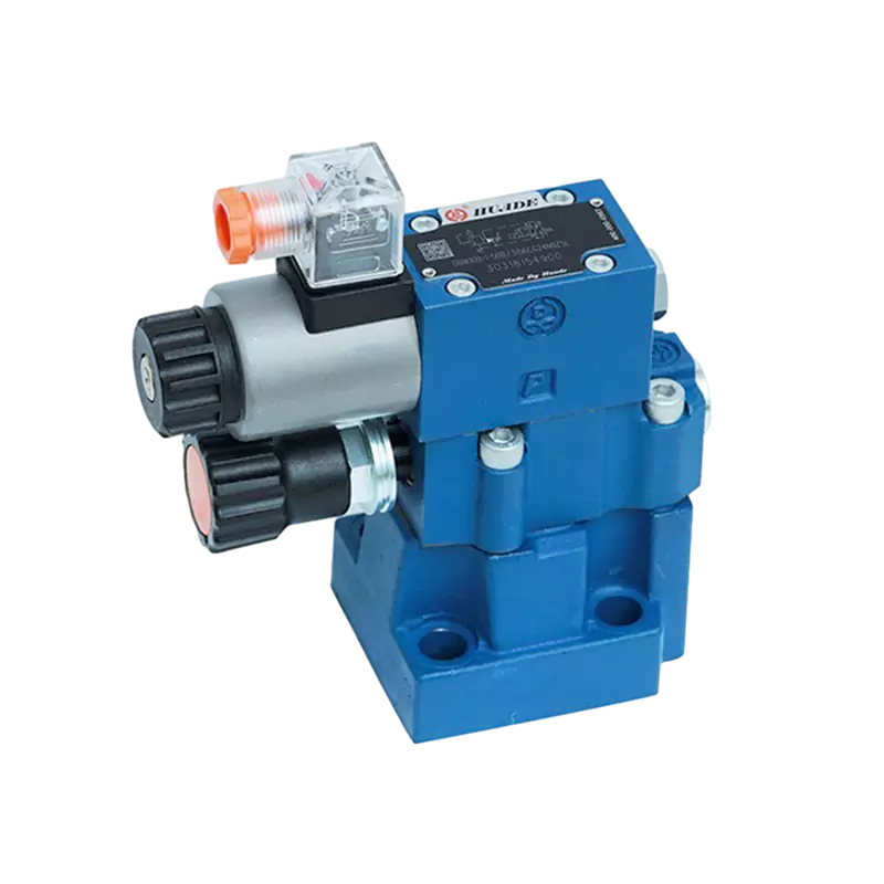
Solenoid actuation represents the most common method in modern hydraulic systems. An electromagnetic coil generates force when energized, pulling an armature that either directly shifts the valve element or controls pilot pressure in a two-stage design. Electrically operated directional control valves integrate seamlessly with programmable logic controllers (PLCs) and enable complex automated sequences.
The choice between these actuation methods depends on control architecture, safety requirements, and environmental constraints. However, within solenoid-actuated valves, a critical subdivision emerges that fundamentally affects flow capacity and electrical efficiency.
Direct-Acting vs Pilot-Operated: Core Operating Principles
Among electrically actuated hydraulic directional control valve types, the distinction between direct-acting and pilot-operated designs represents perhaps the most important performance boundary. These two architectures address the fundamental engineering challenge of generating sufficient force to shift a valve element against fluid forces and spring loads.
Direct-Acting Solenoid Valves
Direct-acting solenoid valves use electromagnetic force from the coil to directly move the main valve spool or poppet. When the coil energizes, the resulting magnetic field pulls the armature, which connects mechanically to the valve element. This straightforward mechanism offers several advantages. Direct-acting valves do not require a pressure differential between inlet and outlet to function, meaning they can operate from 0 bar up to maximum system pressure. This pressure independence makes direct-acting directional control valves essential for applications where the valve must shift before system pressure builds, such as during machine startup sequences or in low-pressure pilot circuits.
The response time of direct-acting valves is typically faster than pilot-operated designs because only one mechanical stage exists. Switching times under 20 milliseconds are achievable with small direct-acting valves, making them suitable for applications requiring rapid cycling.
However, direct-acting designs face severe limitations in flow capacity. The solenoid must generate enough force to overcome fluid forces acting on the valve element, friction forces, and spring return forces. Fluid force increases with both pressure and flow area. As valve size increases to handle higher flow rates, the spool diameter and port sizes must grow, dramatically increasing the fluid forces opposing valve motion. To overcome these larger forces, the solenoid size and electrical power input must increase substantially.
This relationship creates an economic and thermal ceiling. Direct-acting directional control valves handling more than approximately 60 liters per minute at high pressure require solenoids so large and power-hungry that the design becomes impractical. The electrical power may reach 50 to 100 watts or more, generating significant heat that requires dissipation through the valve body and mounting surface. In compact hydraulic systems or densely packed electrical cabinets, this heat load can cause reliability problems.
Pilot-Operated Solenoid Valves
Pilot-operated solenoid valves solve the flow limitation through a two-stage design. The solenoid controls a small pilot valve that directs control fluid to chambers at the ends of the main spool. The pressure difference across the main spool, created by this pilot flow, generates sufficient force to shift the main spool regardless of its size. In this architecture, the solenoid only performs signal generation, requiring far less electrical power than a direct-acting design handling the same flow. Pilot-operated directional control valves can manage hundreds or even thousands of liters per minute while maintaining solenoid power consumption below 10 to 20 watts.
The reduced electrical demand translates to lower heat generation, smaller solenoid housings, and simpler thermal management. For high-flow applications, pilot-operated designs are not just preferable but necessary from both engineering and economic standpoints.
The trade-off for this efficiency gain is pressure dependency. Pilot-operated valves require sufficient pressure differential between the inlet and pilot pressure chambers to generate the force needed for main spool shifting. If system pressure is inadequate during startup or fault conditions, the main spool may not shift completely or may shift sluggishly. Minimum pilot pressures typically range from 3 to 5 bar depending on valve size. Designers must ensure that the pressure source supplying the pilot circuit remains reliable, whether drawn internally from the main pressure line or supplied from an external accumulator or separate pump.
Response time also differs. Pilot-operated valves must fill and drain the pilot chambers at each spool end to create the pressure differential for shifting. This hydraulic delay adds 10 to 50 milliseconds to the switching time compared to direct-acting valves of similar size. For most industrial and mobile applications, this delay remains acceptable, but high-frequency cycling applications may require direct-acting valves despite their flow limitations.
| Performance Aspect | Direct-Acting Solenoid DCV | Pilot-Operated Solenoid DCV |
|---|---|---|
| Actuation Mechanism | Solenoid directly moves valve spool/poppet | Solenoid controls pilot valve; pilot pressure shifts main spool |
| Pressure Differential Requirement | None - operates from 0 bar to max pressure | Requires minimum 3-5 bar differential for reliable shifting |
| Flow Capacity Range | Low to moderate (typically up to 60 L/min) | Moderate to very high (up to 1000+ L/min) |
| Solenoid Power Consumption | High (20-100+ watts for larger sizes) | Low (typically 5-20 watts regardless of flow capacity) |
| Heat Generation | Significant with continuous energization | Minimal |
| Response Time | Fast (typically 10-30 ms) | Moderate (30-80 ms due to pilot circuit filling/draining) |
| Typical Applications | Low flow circuits, zero-pressure starting, pilot control | Main power circuits, high flow systems, mobile equipment |
Engineers selecting hydraulic directional control valve types for a 200 liter per minute excavator circuit would specify pilot-operated valves for the main boom, arm, and bucket functions to minimize electrical heat load and control complexity. However, the same machine might use direct-acting valves in low-flow auxiliary circuits like tool locking mechanisms that must operate reliably at zero system pressure.
Advanced Control: Proportional and Servo Directional Control Valves
While standard directional control valves operate in discrete on-off states, advanced hydraulic directional control valve types provide continuous modulation of flow and pressure through proportional or servo control. These valves represent the high end of performance and complexity.
Proportional directional control valves use proportional solenoids that generate force proportional to input current rather than simple on-off electromagnets. By varying the command signal from a controller, the valve spool position can be adjusted continuously across its full stroke. This allows precise control of actuator speed, acceleration, and force. A proportional valve might control the boom motion of a crane, providing smooth starts, precise positioning, and gentle stops rather than the abrupt motion produced by switching a standard directional control valve on or off.
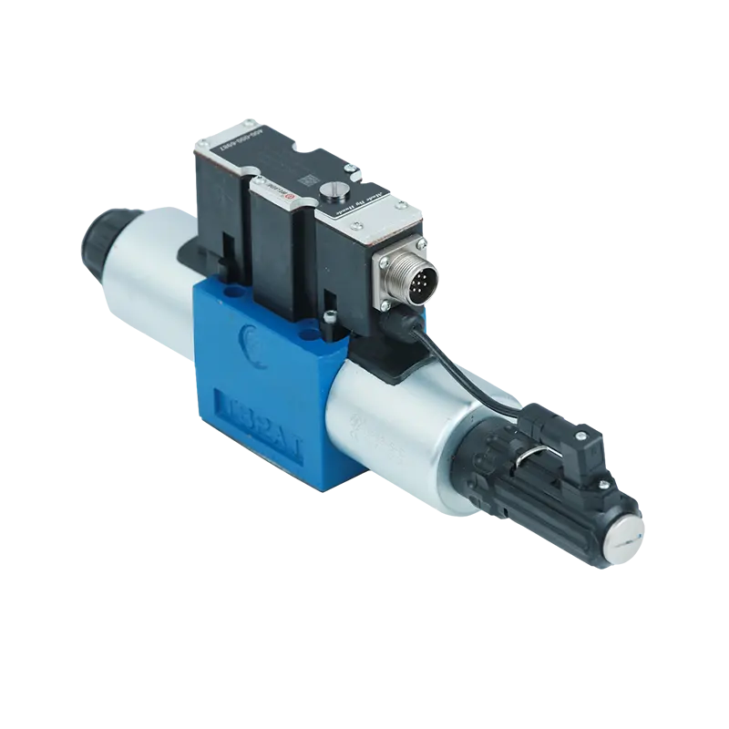
Proportional directional control valves typically include integrated electronics and a position feedback sensor, often a linear variable differential transformer (LVDT), to close the control loop internally. The onboard electronics compare the commanded position to the actual spool position measured by the sensor, adjusting solenoid current to eliminate positioning errors. This closed-loop architecture compensates for variations in friction, fluid forces, and supply pressure that would otherwise cause positioning inaccuracy.
Servo directional control valves extend proportional valve concepts to achieve even higher performance. These valves use torque motors, nozzle-flapper mechanisms, or jet-pipe configurations to achieve response times under 10 milliseconds and frequency response beyond 100 Hz. Servo valves enable applications requiring rapid, precise control such as motion simulators, material testing machines, and active vibration damping systems.
The performance demands of proportional and servo hydraulic directional control valve types drive the need for digital communication interfaces. Traditional analog control signals using 4-20 mA or 0-10 VDC current loops suffer from electrical noise, signal drift, and limited diagnostic capability. As valve response times decrease and positioning requirements tighten, analog signal integrity becomes the limiting factor in system performance.
Digital Integration: IO-Link Protocol in High-Performance Directional Control Valves
The industrial shift toward Industry 4.0 connectivity has produced significant changes in how advanced hydraulic directional control valve types interface with control systems. Digital communication protocols, particularly IO-Link, address the limitations of analog signaling while enabling diagnostic capabilities impossible with conventional wiring.
IO-Link establishes point-to-point digital communication between the valve and a master controller over a standard unshielded cable. This single cable carries power, digital command signals, and bidirectional data communication. Unlike fieldbus networks that require expensive shielded cables and complex network configuration, IO-Link uses simple three-wire connections while maintaining robust noise immunity through digital encoding.
The advantages for proportional and servo directional control valves are substantial. Digital commands eliminate the signal drift and noise pickup that degrade analog precision. Parameter changes can be made through software rather than physical adjustments, dramatically reducing commissioning time. Most importantly, IO-Link provides continuous access to internal valve data including coil temperature, cumulative operating hours, cycle counts, spool position feedback, and detailed error codes.
[Image of IO-Link digital hydraulic valve connectivity diagram]This diagnostic data stream enables condition monitoring strategies that were previously impossible. By tracking coil temperature trends over time, the system can detect gradual degradation of cooling paths or insulation breakdown before catastrophic failure occurs. Monitoring response time drift reveals wear in the pilot stage or contamination-induced friction increases. These insights allow predictive maintenance scheduling that minimizes unplanned downtime.
IO-Link-equipped hydraulic directional control valve types began volume production in July 2022 and are now available in both direct-acting and pilot-operated configurations. The technology supports both proportional and standard on-off valves, though the greatest benefit appears in high-performance applications where signal quality and diagnostic depth justify the modest cost premium.
Selection Criteria for Different Hydraulic Directional Control Valve Types
Selecting appropriate hydraulic directional control valve types requires systematic evaluation across multiple performance dimensions. The decision framework must balance fluid power requirements, electrical constraints, control requirements, and economic factors.
Flow rate stands as the primary determinant. Applications requiring less than 60 liters per minute can use either direct-acting or pilot-operated valves, with the choice driven by pressure availability and response time needs. Systems handling higher flow rates must use pilot-operated valves to avoid excessive solenoid size and heat generation. Attempting to specify direct-acting valves for high-flow applications results in uneconomical designs with severe thermal management challenges.
Operating pressure range matters differently for the two main valve types. Direct-acting directional control valves handle the full pressure range from zero to system maximum, making them mandatory for circuits that must function before pressure builds or during pressure loss scenarios. Pilot-operated valves require minimum pressure differential for reliable operation, typically 3 to 5 bar. Applications where this minimum cannot be guaranteed require direct-acting valves or external pilot supply arrangements.
Control precision needs determine whether standard on-off valves suffice or whether proportional or servo directional control valves are necessary. Simple sequential operations like clamping, extending, or retracting require only discrete position switching. Applications demanding smooth motion profiles, precise positioning, or force regulation require proportional control. Extremely dynamic applications such as active stabilization or high-bandwidth tracking require servo valves despite their higher cost and maintenance requirements.
Fluid cleanliness capabilities must align with valve design sensitivity. Spool-type directional control valves demand strict cleanliness maintenance, typically ISO 4406 18/16/13 or better, with servo valves requiring even tighter control. Applications in contaminated environments or where filtration maintenance may be inconsistent should favor poppet-type valves that tolerate ISO 4406 20/18/15 or slightly higher contamination levels.
Environmental factors influence both valve type and integration approach. Mobile equipment subjected to vibration, temperature extremes, and dirty conditions typically uses pilot-operated poppet valves with robust mechanical interfaces. Industrial automation in controlled environments can leverage spool valves with proportional control and digital networking. Explosive atmospheres may mandate pneumatic actuation or intrinsically safe electrical designs regardless of other preferences.
Electrical power availability and thermal management constraints sometimes override hydraulic considerations. A compact electro-hydraulic unit with limited cooling capacity might specify pilot-operated valves purely to reduce heat generation, accepting the pressure dependency as a necessary trade-off. Conversely, a mobile machine with ample electrical capacity and cooling but operating in load-sensing systems might use direct-acting valves to maintain pressure independence.
The integration architecture increasingly influences selection decisions. Systems designed for Industry 4.0 connectivity should specify proportional or servo directional control valves with IO-Link or fieldbus interfaces to enable diagnostic data collection and predictive maintenance strategies. Traditional systems without data infrastructure may continue using analog or on-off valves until a broader control system upgrade justifies digital conversion.
Common Applications by Hydraulic Directional Control Valve Type
Different hydraulic directional control valve types dominate specific application categories based on their performance characteristics matching industry requirements.
Mobile construction equipment such as excavators, wheel loaders, and bulldozers predominantly use pilot-operated, load-sensing directional control valves in 4/3 configurations. These machines require high flow capacity (often 200 to 600 liters per minute) to power large boom cylinders and travel motors while maintaining reasonable electrical system complexity. The pilot-operated design keeps solenoid power draw low despite high flow rates. Load-sensing circuits with tandem center valves reduce engine fuel consumption during idle periods, a critical advantage in duty cycles with significant waiting time between work cycles.
Agricultural tractors employ similar valve types for implement control but often include electrohydraulic proportional directional control valves for hitches and steering systems where smooth motion improves operator comfort and precision. The harsh, dirty environment typical of agricultural operations favors poppet-style valves in main implement circuits where contamination tolerance outweighs the benefits of proportional spool control.
Industrial injection molding machines use spool-type proportional directional control valves to control mold opening, closing, and ejection sequences. The precise speed control enables optimization of cycle time while preventing damage to molds or parts. The controlled factory environment allows maintenance of the strict fluid cleanliness these servo-quality valves require. Closed-center valve configurations maintain rigid control of mold position under injection pressure loads.
Machine tool hydraulics for milling machines, grinding machines, and lathes typically employ proportional or servo directional control valves controlling axis feed rates and tool clamping. The positioning accuracy and smooth motion essential for surface finish quality demands the continuous modulation capability these valve types provide. In high-end machine tools, servo valves with frequency response exceeding 100 Hz enable vibration damping that improves cutting quality.
Material testing equipment and aerospace simulation systems represent the extreme end of performance requirements. These applications use servo directional control valves with response times under 10 milliseconds and positioning resolution measured in microns. The valves operate with extremely clean fluid, often ISO 4406 15/13/10 or better, and require specialized filtration and conditioning equipment to maintain required cleanliness levels.
Marine deck machinery such as cranes, winches, and hatch covers uses ruggedized pilot-operated directional control valves capable of operating in corrosive saltwater environments. These valves often employ poppet designs for tight shutoff when holding suspended loads and use explosion-proof solenoid enclosures to meet maritime safety standards.
Simple pneumatic circuits controlling hydraulic presses, lift tables, or material handling equipment often use basic direct-acting 4/2 or 4/3 directional control valves. These applications value simplicity and low cost over advanced features, and their modest flow requirements (typically under 40 liters per minute) remain within direct-acting valve capabilities.
Emerging Trends in Hydraulic Directional Control Valve Technology
The evolution of hydraulic directional control valve types continues along several parallel paths driven by Industry 4.0 integration, energy efficiency mandates, and miniaturization demands.
Digital communication protocols are expanding beyond high-performance proportional and servo valves into standard on-off directional control valves. As the incremental cost of IO-Link interface electronics decreases, even basic 4/3 valves now offer digital connectivity options. This democratization of diagnostic data enables condition monitoring across entire hydraulic systems rather than just premium components, improving overall equipment effectiveness (OEE) through better maintenance planning.
Energy efficiency pressure drives adoption of advanced center position designs and load-sensing hydraulics. Modern mobile equipment increasingly uses proportional directional control valves with electronic control units that implement sophisticated pressure compensation algorithms, reducing the power losses inherent in traditional flow dividers and priority valves. Some systems now employ individual electric motors driving small pumps at each actuator, eliminating the directional control valve entirely in a shift toward electro-hydraulic actuators (EHAs).
Valve integration continues compressing multiple functions into single bodies. Manifold-mounted directional control valves increasingly incorporate pressure compensation, load-holding check valves, and electronic control directly in the valve assembly rather than requiring separate components. This integration reduces leak points, simplifies assembly, and decreases the physical footprint of hydraulic systems.
Contamination tolerance improvements focus on extending service intervals and reducing total cost of ownership. Some manufacturers now offer hybrid designs combining the contamination tolerance of poppet valves with continuous flow modulation approaching spool valve performance through sophisticated seat geometries and control algorithms.
Functional safety requirements from standards such as ISO 13849 and IEC 61508 increasingly influence directional control valve design. Safety-rated valves include redundant sensors, diagnostic coverage for potential failure modes, and integrated monitoring that detects dangerous faults. These features allow hydraulic systems to achieve required safety integrity levels (SIL 2 or SIL 3) previously difficult to attain with fluid power components.
Understanding the full spectrum of hydraulic directional control valve types enables engineers to make informed decisions that optimize system performance, reliability, and cost. The classification by way and position numbers, valve element design, actuation method, and operating principle provides a structured framework for valve selection. Within this framework, the fundamental distinction between direct-acting and pilot-operated designs sets flow capacity boundaries that no amount of design optimization can overcome. Proportional and servo technologies extend control precision for demanding applications while driving adoption of digital interfaces that transform valves from passive components into intelligent nodes in networked control architectures. As hydraulic systems evolve toward greater integration with industrial networks and higher efficiency standards, matching valve capabilities to application requirements becomes increasingly sophisticated, requiring deep knowledge of both fluid mechanics and control systems engineering.


