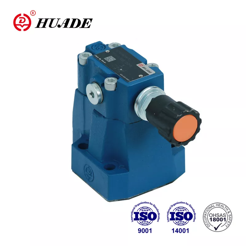
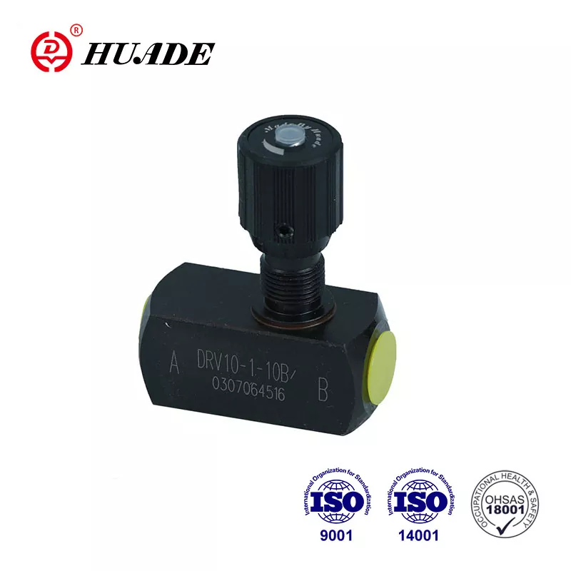
When a directional control valve stops working properly, it can bring an entire hydraulic system to a halt. These valves act as the "traffic directors" of fluid power systems, telling hydraulic fluid where to go and when. But what actually causes these critical components to fail?
The root causes of directional control valve failure typically include contamination (responsible for 70-80% of failures), mechanical wear, electrical problems, seal deterioration, and improper installation. While symptoms like valve sticking or leakage are what operators notice first, the underlying mechanisms often involve complex interactions between fluid chemistry, mechanical stress, and thermal effects.
This article examines the failure modes that maintenance engineers and hydraulic technicians encounter most frequently in industrial settings. Understanding these mechanisms helps move maintenance strategy from reactive repairs to predictive prevention.
Contamination: The Primary Culprit
Contamination stands as the single largest cause of hydraulic valve failures across industries. Research consistently shows that 70 to 90 percent of all hydraulic system problems trace back to contaminated fluid. The challenge lies in understanding that contamination comes in two distinct forms, each attacking valve components through different mechanisms.
Hard particle contamination includes dust, metal chips, and abrasive debris that enter the system during assembly, maintenance, or through damaged seals. These particles act like sandpaper inside the valve body. The precision fit between a spool and its bore typically measures only 2 to 5 micrometers (0.00008 to 0.0002 inches) - thinner than a human hair. When particles larger than this clearance enter the gap, they become trapped between the moving surfaces and cause three-body abrasion.
The abraded material creates microscopic grooves on the highly polished spool lands. These grooves destroy the sealing capacity of the valve and create fluid bypass paths. High-pressure fluid then flows directly to the tank port through these scratches, causing actuators to drift even when the valve should be holding position. The damage becomes self-perpetuating because the wear debris generated by initial scratching creates more abrasive particles.
Different valve types show vastly different sensitivity to particle contamination. Servo valves with nozzle-flapper assemblies fail when particles as small as 1-3 micrometers block the pilot orifices. Standard solenoid directional valves tolerate somewhat larger particles but still require careful filtration. The ISO 4406 cleanliness code provides the standard for measuring fluid contamination levels, using three numbers to represent particle counts above 4, 6, and 14 micrometers per milliliter of fluid.
| Valve Type | Sensitivity Level | Target ISO 4406 Code | Typical Clearance | Failure Risk |
|---|---|---|---|---|
| Servo Valves | Critical | 15/13/10 or better | 1-3 μm | Pilot orifices clog easily; minor contamination causes control failure |
| Proportional Valves | High | 17/15/12 | 2-5 μm | Increased friction causes hysteresis and reduced control accuracy |
| Solenoid Directional Valves | Moderate | 19/17/14 | 5-10 μm | Can tolerate some contamination but long-term exposure causes seal wear |
| Manual Lever Valves | Low | 20/18/15 | >10 μm | Manual force can overcome friction from light contamination |
Studies demonstrate that improving fluid cleanliness from ISO 20/18/15 to 16/14/11 can extend component life by three to four times. Maintenance teams that ignore these targets see premature valve failure regardless of other preventive measures.
The second contamination threat comes from soft deposits called varnish or lacquer. Unlike hard particles that filtration can remove, varnish forms through chemical reactions within the hydraulic fluid itself. High temperatures above 60°C (140°F) trigger oxidation of the base oil, especially when catalyzed by dissolved copper or iron from system wear. The oxidation products initially dissolve in the fluid but gradually polymerize into sticky, insoluble compounds.
Varnish deposits preferentially accumulate on metal surfaces in low-flow areas, particularly around the spool ends and control chambers. The material acts like glue, filling the critical clearance between spool and bore. Temperature sensitivity creates a characteristic failure pattern known as "Monday morning sickness." During operation, warm oil keeps varnish deposits soft and semi-dissolved, allowing the valve to function. When equipment sits idle over a weekend, the fluid cools and the varnish hardens into a rigid coating that mechanically locks the spool in place. Operators attempting to start the system on Monday morning find valves that refuse to shift. As the system warms up through relief valve bypassing, the varnish softens again and the fault mysteriously disappears.
Traditional oil analysis methods using spectrometry cannot detect varnish precursors because they exist as submicron soft particles. The Membrane Patch Colorimetry (MPC) test following ASTM D7843 provides the only reliable early warning. This test passes oil through a 0.45-micrometer filter membrane, trapping insoluble degradation products that stain the membrane. A spectrophotometer measures the color intensity in the CIE Lab color space, producing a ΔE value. Values below 15 indicate low varnish risk, while readings above 30-40 signal imminent valve sticking and require immediate intervention with electrostatic filtration or ion exchange resin systems.
Mechanical Wear and Component Fatigue
Even in perfectly clean systems, repeated pressure cycles gradually wear down valve components through normal operational stress. The failure mechanisms differ fundamentally from contamination damage but eventually produce similar symptoms of valve malfunction.
Seal rings and backup rings experience continuous compression and relaxation as system pressure fluctuates. The elastomeric material undergoes permanent deformation through a process engineers call compression set. After millions of cycles, O-rings lose their ability to spring back to original shape. The reduced interference fit allows increased internal leakage past the spool. Cylinder drift becomes noticeable as the valve can no longer hold pressure effectively. Temperature accelerates this aging process - seals operating at 80°C (176°F) degrade roughly twice as fast as those at 40°C (104°F).
Return springs face similar fatigue challenges in high-cycle applications. These springs provide the force to center the spool or return it to the neutral position after solenoid de-energization. The constant compression cycles cause metal fatigue that gradually reduces the spring constant. Weakened springs may lack sufficient force to overcome hydraulic pressure or friction, causing the spool to hang in shifted position. In extreme cases, stress corrosion cracking occurs when water contamination combines with mechanical stress, leading to sudden spring fracture and complete loss of valve control.
The spool itself experiences wear at the lands where it slides against the bore. Microscopic surface irregularities create high-stress contact points that gradually polish away. This radial wear increases the clearance dimension, allowing more leakage. The wear pattern typically shows asymmetry because pressure distribution around the spool circumference varies with port configurations. One side wears faster than others, potentially causing the spool to cock slightly in the bore and increase friction.
Seat valves face different mechanical challenges than spool valves. Rather than wearing through sliding motion, seat valves depend on a cone or ball pressing against a matching seat surface to achieve sealing. The contact stress concentrates on a narrow line around the seat. If a hard particle becomes trapped on this sealing surface, system pressure drives the particle into the softer metal, creating a permanent impression or pit. Even after removing the particle, the damaged seal line allows leakage. This failure mode explains why seat valves often shift from perfect sealing to substantial leakage with little warning.
Electrical and Solenoid Failures
The electrical interface between control systems and hydraulic valves introduces failure modes that mystify technicians who focus only on mechanical causes. Solenoid coil burnout ranks among the most reported valve failures, but analysis reveals that electrical problems usually result from mechanical root causes rather than pure electrical faults.
AC (alternating current) solenoid valves demonstrate particularly tight coupling between mechanical and electrical behavior. The coil impedance depends primarily on inductive reactance, which varies inversely with the air gap in the magnetic circuit. When voltage first applies to an AC solenoid, the armature sits at maximum distance from the pole face, creating maximum air gap and minimum inductance. Low inductance means low impedance, allowing inrush current that may reach 5 to 10 times the normal holding current to flow through the coil windings.
Under normal operation, electromagnetic force pulls the armature closed within milliseconds. The collapsing air gap dramatically increases inductance, raising impedance and dropping current to safe steady-state levels. The entire sequence depends on free mechanical movement of the armature and spool assembly. If varnish deposits, particle contamination, or mechanical binding prevents the spool from completing its stroke, the air gap remains open. The coil continues drawing massive inrush current indefinitely. According to Joule's law (Q = I²Rt), the heat generated in the coil rises with the square of current. Within seconds to minutes, winding insulation melts, causing turn-to-turn shorts that generate even more heat until the coil fails completely.
This mechanism explains why simply replacing a burned coil without investigating mechanical sticking guarantees repeated failure. The new coil burns out immediately upon energization if the underlying mechanical problem persists. Diagnostic procedures must always include manual override testing - physically pushing the valve spool with a hand actuator to verify smooth movement before assuming electrical fault.
DC (direct current) solenoids exhibit more benign failure patterns because their current depends only on voltage and resistance (I = V/R), independent of armature position. A mechanically stuck DC valve simply fails to shift but rarely burns out the coil. DC solenoid failures typically trace to true electrical causes like overvoltage exceeding rated values by more than 10 percent, excessive ambient temperature preventing heat dissipation, or moisture ingress causing internal shorts.
Another mechanical-electrical interaction occurs in the core tube (armature guide). This thin-walled tube isolates the armature from hydraulic fluid while allowing magnetic flux to pass. Excessive installation torque on the solenoid mounting nut or abnormal pressure spikes can deform the tube, creating tight spots that drag on the armature. The solenoid generates insufficient force to overcome this added friction, resulting in "energized but no movement" failures that appear electrical but stem from mechanical causes.
Seal Degradation and Chemical Incompatibility
Seals represent the most chemically vulnerable components in directional control valves. While metal parts resist most hydraulic fluids, elastomeric seals can suffer catastrophic failure when exposed to incompatible chemicals. The failure mode differs completely from wear-related deterioration and often occurs rapidly after fluid changes or seal replacement with incorrect materials.
Chemical attack manifests primarily through swelling and softening. When seal material lacks compatibility with the hydraulic fluid, fluid molecules penetrate the polymer matrix causing volumetric expansion. The swollen seal exceeds the groove dimensions and creates high interference with moving parts. Nitrile rubber (NBR or Buna-N) seals exposed to phosphate ester fire-resistant fluids like Skydrol demonstrate this dramatically. The NBR absorbs fluid and swells severely, transforming into a soft gel-like mass. The expanded seal generates enormous friction against the spool and can completely prevent valve operation within hours. Shear forces tear pieces from the softened rubber, creating debris that plugs pilot passages and damages downstream components.
Proper seal material selection requires matching the elastomer chemistry to the specific hydraulic fluid in use. The challenge intensifies in systems that convert from mineral oil to synthetic fluids or switch between different fire-resistant formulations. What works perfectly in one application causes immediate failure in another.
| Hydraulic Fluid Type | Nitrile (NBR) | Fluorocarbon (Viton/FKM) | EPDM Rubber | Polyurethane |
|---|---|---|---|---|
| Mineral Oil | Excellent | Excellent | Severe Damage | Excellent |
| Phosphate Ester (Skydrol) | Severe Damage | Moderate/Poor | Excellent | Severe Damage |
| Water Glycol | Good | Good | Good | Poor (Hydrolysis) |
| Biodegradable Ester (HEES) | Fair | Good | Poor | Fair |
The table reveals critical relationships - EPDM performs excellently in phosphate ester systems but fails catastrophically in mineral oil, showing the exact opposite pattern from NBR. Fluorocarbon seals (Viton) offer broad compatibility but cost significantly more and show only moderate performance in some fire-resistant fluids. Technicians must verify seal material codes during maintenance and ensure replacement parts match the fluid chemistry.
High-pressure applications introduce a purely mechanical seal failure mode called extrusion or nibbling. At pressures exceeding 20 MPa (3000 psi), O-rings behave more like viscous fluids than elastic solids. If the clearance between mating metal parts exceeds design limits due to wear or machining tolerance stack-up, system pressure forces rubber into the gap. Pressure pulsations cause the extruded portion to repeatedly squeeze out and pull back. The metal edges act like scissors, cutting small pieces from the seal with each pressure cycle. The damaged seal shows characteristic chewed appearance on the low-pressure side. Engineers prevent extrusion in high-pressure applications by installing backup rings made from PTFE (polytetrafluoroethylene) on the low-pressure side of each O-ring, physically blocking the extrusion path.
Temperature extremes also degrade seals through mechanisms unrelated to chemical compatibility. Prolonged heat exposure above the seal's temperature rating causes hardening and loss of elasticity. The brittle seal cracks under compression, creating permanent leak paths. Cold temperatures below the glass transition point produce similar brittleness. Seals that flex while cold may fracture catastrophically. The temperature specifications in seal catalogs represent critical selection criteria that maintenance teams sometimes overlook.
Fluid Dynamics Issues: Cavitation and Erosion
The high-velocity fluid flow through valve ports and passages creates forces capable of physically destroying metal surfaces. These fluid dynamic failure modes differ from contamination or wear because the damage comes from the fluid itself rather than foreign particles or repeated motion.
Cavitation occurs when local pressure drops below the vapor pressure of the hydraulic fluid, causing it to boil and form vapor bubbles. According to Bernoulli's principle, fluid velocity increases dramatically as it passes through the narrow opening at the valve port, with corresponding pressure decrease. If this pressure drop brings the static pressure below the fluid's vapor pressure at operating temperature, vapor cavities rapidly form in the liquid stream.
The destructive phase begins when these vapor-filled bubbles flow downstream into regions of higher pressure. Unable to sustain themselves, the bubbles collapse violently in a process called implosion. Each collapsing bubble generates a microscopic high-velocity jet that can reach supersonic speeds and produce local pressures exceeding several thousand bar. When these micro-jets repeatedly strike metal surfaces, they erode material away through a mechanism similar to water jet cutting. The damaged surfaces develop characteristic spongy pitting that destroys the precisely machined metering edges on valve spools.
Operators can often detect cavitation before visual inspection reveals damage because it produces distinctive acoustic signatures. The repeated bubble collapse creates noise that sounds like gravel shaking in a container or high-pitched squealing. Systems running near cavitation threshold show intermittent noise that comes and goes with load changes. The noise correlates directly with progressive metal erosion, making acoustic monitoring a valuable predictive maintenance tool.
A related but distinct failure mode called wire-drawing erosion affects valve seating surfaces. When a valve should be closed but fails to seal completely due to particles holding the seat open or surface damage, high-pressure fluid forces through the microscopic gap at extreme velocity. Flow speeds can reach hundreds of meters per second through these tiny leaks. The fluid jet cuts through metal like a water knife, carving narrow grooves that resemble scratches from fine wire. Once wire-drawing damage begins, the leak area increases rapidly and the valve loses all pressure-holding capability.
The pressure differential across the valve determines cavitation and erosion intensity. Design engineers select valves with appropriate flow capacity to keep pressure drops within acceptable limits. Operating valves at higher pressure differentials than their design rating accelerates fluid dynamic damage. Systems with inadequate pilot drain lines or blocked tank ports create back pressure that forces the main spool to operate with excessive pressure drop, triggering cavitation even though system specifications appear normal.
Installation and Mechanical Stress Factors
Mechanical factors related to valve mounting and system design create failure modes that perplex troubleshooters because the valve appears defective immediately after installation, yet operates freely when removed from the system. These installation-induced failures result from elastic deformation of the valve body under stress from mounting forces.
Directional control valves mounting on subplates or manifolds require uniform clamping force across multiple mounting bolts. Uneven torque application causes the valve body to twist slightly. While this deformation may measure only a few micrometers, it becomes critical for valves where spool-to-bore clearance runs just 2-5 micrometers. A circular bore twisted into an ellipse will pinch the cylindrical spool at opposing points, dramatically increasing friction or completely jamming the spool.
The failure signature reveals itself clearly - a new valve that refuses to shift when bolted to the system moves freely when held in hand. Technicians who lack awareness of this mechanism often blame the valve manufacturer and initiate unnecessary warranty returns. The actual cause lies in improper installation procedure. Valve manufacturers specify torque values and tightening sequences for mounting hardware. Following these specifications maintains bore geometry within tolerance. Excessive torque or corner-to-corner tightening patterns introduce twisting stress that oval-izes the bore.
Subplate flatness represents another critical installation parameter. If the mounting surface shows waviness or raised areas from weld spatter or corrosion, the valve body conforms to these irregularities when bolted down. The resulting body distortion creates internal misalignment between spool and bore. Engineers specify maximum flatness deviation, typically around 0.025 mm (0.001 inch) across the valve mounting surface. Maintenance teams sometimes ignore this specification, particularly during field repairs or system modifications.
Cartridge-style valves installed in manifold cavities face similar challenges. The thread torque and cavity depth both influence how the cartridge seats. Over-torquing threads can deform the thin walls of the cartridge body. Incorrect cavity depth leaves the cartridge in tension or compression, either of which distorts internal clearances. These installation errors manifest as valves that worked perfectly on the test bench but stick or leak when installed in the production manifold.
Vibration and shock loading introduce dynamic stresses that fatigue metal components over time. Directional valves mounted on mobile equipment or reciprocating machinery experience acceleration forces that crack mounting bosses, break retaining pins, and loosen threaded connections. The mechanical shock from water hammer - pressure surges created when valves close rapidly - can exceed the valve's rated pressure by multiples. Repeated pressure spikes work-harden metal surfaces and cause fatigue cracks that eventually result in housing rupture or spool fracture.
Diagnostic Approaches for Directional Control Valve Failures
Effective troubleshooting requires systematic investigation that isolates the failure mechanism before replacing components. The following diagnostic sequence works from simple external checks toward invasive internal inspection, minimizing downtime while gathering definitive root cause data.
Visual and sensory inspection forms the first step. External fluid leakage around housing joints or seal glands indicates O-ring failure. Burn marks or melted plastic on solenoid coils confirm electrical overheating. The distinct odor of burned coil insulation differs markedly from normal hydraulic oil smell. Cavitation produces characteristic noise that trained technicians recognize immediately. Recording baseline acoustic signatures during proper operation enables comparison when problems arise.
Manual override testing provides the critical mechanical versus electrical differentiation. Almost all solenoid directional valves include a manual push pin or button that mechanically forces the spool to shift. If the valve responds to manual actuation and the system operates normally, the valve mechanism functions correctly and the problem lies in electrical control circuits. Conversely, inability to manually shift the spool confirms mechanical binding from contamination, varnish, or deformation. This simple test takes seconds but eliminates hours of wasted effort chasing the wrong failure mode.
Electrical verification requires measuring both coil resistance and actual operating voltage. Resistance readings falling outside the specification range (typically 50-200 ohms for DC coils, 10-50 ohms for AC coils) indicate coil damage. However, resistance alone tells an incomplete story. Measuring voltage at the solenoid connector under load reveals voltage drop from loose connections or undersized wiring. A solenoid rated for 24 VDC that receives only 18 VDC due to wire resistance may generate insufficient force to shift the spool against friction and pressure forces. The electromagnetic force varies with voltage squared (F ∝ V²), making voltage drop particularly damaging.
Internal leakage quantification requires hydraulic testing equipment. The most practical method for mobile equipment involves blocking the valve ports and pressurizing them individually while measuring flow to tank. Comparing measured leakage against manufacturer specifications determines whether internal wear has progressed beyond acceptable limits. For stationary equipment, observing actuator drift under load provides functional leakage assessment. An actuator that slowly extends or retracts when the valve sits in neutral position indicates excessive internal leakage allowing pressure to reach the wrong chamber.
Thermal imaging offers a non-invasive technique for detecting internal leakage before it becomes critical. High-velocity flow through wear-enlarged clearances generates heat through throttling. An infrared camera scanning the valve body reveals hot spots at locations with abnormal internal flow. Temperature differentials of 10-20°C above surrounding areas indicate significant leakage paths. This early warning allows scheduled maintenance before complete failure stops production.
Oil analysis laboratories test fluid samples for both particle contamination and chemical degradation. Particle counting determines ISO 4406 cleanliness code and identifies whether filtration systems function properly. Acid number testing reveals oxidation level. Most importantly for varnish-related problems, requesting MPC analysis provides early warning of sticky deposit formation before valves start sticking. A comprehensive oil analysis program catches contamination problems before they destroy expensive valves.
| Symptom | Probable Cause | Diagnostic Check | Remedy |
|---|---|---|---|
| Valve does not shift |
1) Coil burned/open 2) Spool stuck from varnish 3) Body distortion |
1) Measure coil resistance 2) Try manual override 3) Slightly loosen mounting bolts |
1) Replace coil and fix sticking 2) Clean valve, install varnish filter 3) Retorque per specification |
| Coil burns repeatedly |
1) Spool binding causes AC inrush 2) Overvoltage 3) High cycle rate |
1) Check spool friction 2) Measure terminal voltage 3) Review control logic |
1) Fix binding or switch to DC 2) Correct power supply 3) Improve cooling or reduce cycles |
| Actuator drifts |
1) Internal wear/leakage 2) Seal failure 3) Contaminated fluid |
1) Block ports and measure pressure decay 2) Check return line flow 3) Test fluid cleanliness |
1) Replace valve 2) Replace seals 3) Filter oil to ISO target |
| Excessive noise |
1) Cavitation 2) AC solenoid buzz |
1) Analyze noise frequency 2) Inspect armature face for dirt |
1) Increase back pressure, eliminate air 2) Clean pole faces or switch to DC |
The troubleshooting guide synthesizes symptom-cause-solution relationships that field technicians encounter most frequently. Following this structured approach reduces diagnostic time while increasing fix-it-right-the-first-time success rates.
Moving Toward Predictive Maintenance
Understanding failure mechanisms enables the transition from reactive breakdown maintenance to predictive condition-based maintenance strategies. Rather than waiting for valves to fail during production, predictive approaches detect degradation early and schedule repairs during planned downtime.
Establishing baseline performance metrics provides the foundation for predictive programs. Recording new valve characteristics including manual actuation force, electrical current draw, internal leakage rate, and acoustic signature creates reference data. Periodic measurements showing deviation from baseline trigger investigation before complete failure occurs.
Contamination control deserves primary focus given its responsibility for the majority of failures. Regular oil sampling with both particle counting and MPC testing catches problems before valves stick. Systems showing ISO cleanliness codes exceeding target values require immediate filtration system inspection and potentially filter element replacement. MPC ΔE values rising above 30 demand installation of electrostatic or resin-based varnish removal systems.
Component replacement intervals should reflect actual operating conditions rather than arbitrary time periods. Valves cycling millions of times per year require more frequent seal replacement than seldom-operated valves. Temperature, fluid type, and pressure levels all influence degradation rates. Collecting failure history data enables statistical life prediction customized to specific applications. Some operations implement valve cycling counters that trigger maintenance based on actual usage rather than calendar time.
Training maintenance personnel in proper installation procedures prevents the mechanical stress failures that frustrate troubleshooters. Creating documented procedures with specified torque values, tightening sequences, and flatness checks ensures consistent results across shifts and technicians. Torque wrenches should be calibrated regularly and required for all valve installation work.
System design reviews can identify conditions that accelerate valve wear. Inadequate pilot drain lines, missing pressure shock suppressors, and incorrect valve sizing all contribute to premature failure. Addressing these system-level issues reduces failure frequency more effectively than simply replacing valves with identical units that face the same damaging conditions.
The cost-benefit analysis strongly favors predictive maintenance for critical systems where valve failure causes expensive downtime. While predictive programs require investment in testing equipment and training, the return comes through eliminated unplanned outages, extended component life, and reduced emergency repair costs. Plants that implement comprehensive predictive programs typically see valve-related failures decrease by 60-80 percent within two years.
Conclusion
Directional control valve failure results from multiple interacting mechanisms rather than single isolated causes. Contamination dominates the failure statistics but manifests through different physical processes - hard particles cause abrasive wear while soft varnish deposits create chemical sticking. Electrical failures usually trace to mechanical binding that prevents proper solenoid operation. Seal degradation reflects chemical incompatibility or mechanical extrusion more often than simple aging. Fluid dynamic forces damage precise surfaces through cavitation and high-velocity erosion. Installation stress introduces geometric distortion that binds moving parts.
Effective failure prevention requires system-level thinking that extends beyond the valve itself. Fluid cleanliness according to ISO 4406 standards appropriate for valve type forms the foundation. Chemical compatibility between seals and hydraulic fluid prevents catastrophic swelling failures. Proper installation procedures maintain critical internal clearances. Addressing system design issues that create excessive pressure drop or inadequate cooling extends valve service life dramatically.
The transition from reactive maintenance to predictive condition monitoring separates high-performance operations from those plagued by unexpected failures. Oil analysis programs, thermal imaging surveys, and acoustic monitoring detect problems during early stages when corrective action costs little and requires no emergency downtime. Understanding the fundamental physics and chemistry behind valve failures transforms maintenance from parts replacement into reliability engineering.


