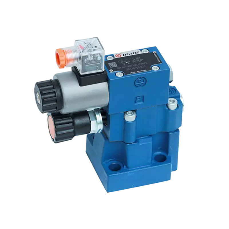
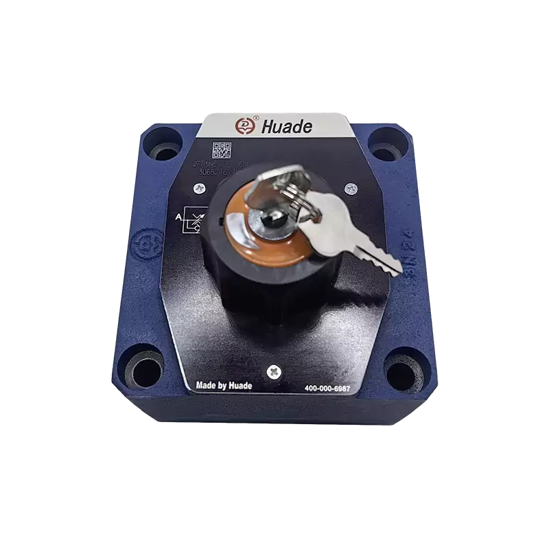
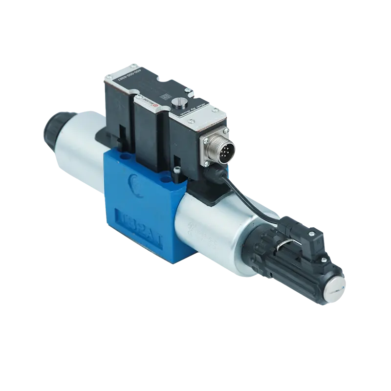
A 2 way hydraulic directional control valve is one of the simplest yet most essential components in fluid power systems. The name tells you exactly what it does: it has two fluid ports and two distinct working positions. Think of it as a sophisticated on-off switch for hydraulic oil, similar to how a water faucet controls flow in your home.
The two ports are typically called inlet and outlet, though in hydraulic systems these terms can be flexible depending on your circuit design. Unlike more complex valves that have separate P (pressure), T (tank), A and B (work) ports, a 2 way valve focuses on one fundamental task: allowing flow between two points or blocking it completely.
These valves exist in two basic configurations. A normally closed (NC) valve stays shut when no power or force is applied, blocking all flow. Once you activate it, the valve opens and fluid can pass through. A normally open (NO) valve works the opposite way, it starts open and closes when activated. The choice between these two depends entirely on what happens when your system loses power. For safety-critical applications, you need to think carefully about whether you want flow or no flow in a power-loss scenario.
The beauty of a 2 way hydraulic directional control valve lies in its simplicity. By handling just the basic permit or deny function, these valves become building blocks for more complex hydraulic logic. You can combine multiple 2 way valves in a manifold block to create sophisticated control circuits while maintaining excellent sealing and reliability.
Core Design Types: Poppet vs Spool Construction
When engineers select a 2 way hydraulic directional control valve, the biggest decision comes down to internal structure. Two designs dominate the market, and each makes a different engineering trade-off between sealing performance and flow capacity.
Poppet Valve Design: Maximum Sealing Performance
Poppet valves use a cone-shaped or ball-shaped element that presses against a precision seat to block flow. When force is applied (by a spring or actuator), this element lifts off the seat and fluid passes through. The physical contact between the poppet and seat creates what engineers call a hard seal.
This design delivers exceptional leakage control. High-quality poppet-type 2 way valves can achieve near-zero internal leakage, often less than 0.7 cc/min (about 10 drops per minute) even at pressures reaching 350 bar or 5000 psi. For applications where you need to hold a load for hours or days without any drift, nothing beats a poppet valve.
[Image of cross section diagram of poppet hydraulic valve vs spool hydraulic valve]The short stroke of the poppet element also enables fast response times. Many direct-acting poppet valves switch in approximately 50 milliseconds. The simple design with fewer moving parts typically translates to longer service life and lower maintenance requirements. Premium poppet designs can provide bi-directional sealing, meaning they block flow effectively regardless of which direction pressure is applied from.
Spool Valve Design: High Flow Capacity
Spool valves take a different approach. A cylindrical element (the spool) slides inside a precision-bored chamber. The spool has raised sections called lands and recessed sections called grooves. As the spool moves, these features either block ports or connect them through internal passages.
The fundamental limitation of spool valves is clearance leakage. There must be a small gap between the spool and bore for the spool to move freely, and fluid inevitably leaks through this gap. But what spool valves give up in sealing, they gain in flow capacity.
Recent innovations have dramatically improved spool valve flow capabilities. By designing multiple internal flow paths within the valve body and spool grooves, manufacturers have found ways to multiply flow capacity without increasing the spool diameter. Some advanced pilot-operated spool-type 2 way valves now handle flows up to 1,100 liters per minute while keeping the valve body reasonably compact.
This structural innovation matters because traditionally, increasing flow meant making the spool larger in diameter. Larger spools require more force to move and more complex machining. The multi-path approach lets you use standard manufacturing equipment while dramatically improving rated flow. For applications like rapid pump unloading in high-power hydraulic systems, this flow capacity makes spool valves the only practical choice.
| Performance Factor | Poppet Valve | Spool Valve |
|---|---|---|
| Internal Leakage | Near zero (<0.7 cc/min at 350 bar) | Moderate (clearance leakage present) |
| Sealing Mechanism | Hard physical contact with seat | Precision clearance fit |
| Maximum Flow Capacity | Limited by poppet size | Very high (up to 1,100+ L/min with multi-path design) |
| Response Speed | Fast (short stroke, ~50 ms) | Fast but depends on actuation force |
| Service Life | Long (less wear) | Good (requires clean fluid) |
| Best Applications | Load holding, accumulator isolation, zero-leak circuits | High flow switching, pump unloading, high power density |
The selection between poppet and spool designs represents a classic engineering decision point. If your application involves static high-pressure holding (like hydraulic clamping or accumulator isolation), the zero-leakage characteristic of a poppet valve is essential. But if you need dynamic high-flow switching (like rapid pump unloading), the flow capacity of a spool valve becomes the critical requirement.
How These Valves Are Operated: Actuation Methods
A 2 way hydraulic directional control valve needs force to change position. The method you use to generate that force significantly affects the valve's response speed, pressure capacity, and reliability. Two electrical actuation approaches dominate industrial applications.
Direct-Acting Solenoid Valves
In a direct-acting design, an electromagnetic coil pulls on an armature that directly connects to the valve element. When you energize the coil, the magnetic force immediately moves the poppet or spool.
The main advantage is speed. Direct-acting 2 way valves typically respond in about 50 milliseconds from the moment you apply power. Just as importantly, these valves do not depend on system pressure to operate. They work reliably during system startup or in low-pressure conditions. For safety-critical functions like accumulator discharge circuits, direct-acting poppet valves can be spring-returned, meaning they automatically return to a safe position if electrical power fails, with no minimum hydraulic pressure required.
Recent developments in low power solenoid valve (LPSV) technology have transformed the efficiency landscape. Traditional solenoid valves might consume 10-20 watts continuously. Modern LPSV designs have reduced power consumption to as low as 1.4 watts, with some specialized units reaching 0.55 watts.
This reduction in power creates several practical benefits. Lower power consumption means less heat generation, which directly extends coil life and reduces thermal stress on seals and other components. In wet armature designs (where hydraulic fluid surrounds the solenoid core), excessive heat can cause certain fluids like water-glycol mixtures to break down and form varnish deposits on the moving parts. By minimizing heat from the source, LPSV technology addresses this long-term degradation mechanism.
From a system perspective, lower power also means you can operate more valves from the same power supply and control circuitry. In hazardous environments like oil and gas applications, reduced power consumption decreases the risk of ignition sources. Many LPSV valves can meet intrinsically safe requirements, significantly improving safety ratings in explosive atmospheres.
Pilot-Operated Solenoid Valves
Pilot-operated valves use a small direct-acting valve to control system pressure, which then provides the force to move the main valve element. The solenoid only needs to shift a tiny pilot poppet. System pressure acting on a piston or spool does the heavy lifting of moving the main flow control element.
[Image of diagram of pilot operated hydraulic valve internal structure]This approach allows much higher flow and pressure capabilities than direct-acting designs. Pilot-operated 2 way hydraulic directional control valves can handle flows approaching or exceeding 1,000 liters per minute and pressures up to 500 bar. The solenoid itself remains small and low-power because it only controls the pilot stage.
However, pilot operation creates inherent compromises. Response time increases significantly, typically to 100 milliseconds or longer. The valve needs time for pilot pressure to build and for that pressure to move the larger main element. The design complexity increases because you now have pilot passages, often with small orifices for pressure control. These small passages make pilot-operated valves more sensitive to fluid contamination. A particle that would pass harmlessly through a direct-acting valve can block a pilot orifice and prevent the main valve from shifting.
Pilot-operated valves also require minimum system pressure to function. If pressure drops below the threshold needed to move the main spool, the valve may not shift fully or at all, even though the pilot stage is working correctly. This dependency makes them less suitable for applications requiring operation during startup or in fail-safe scenarios where system pressure might be lost.
Managing Dynamic Response and System Shock
Fast valve response sounds universally desirable, but it creates its own problems. When a 2 way valve closes in 50 milliseconds, it suddenly stops moving fluid. This rapid change in flow velocity creates pressure spikes, sometimes called water hammer, which can damage components.
Many manufacturers now offer soft shift mechanisms for 2 way hydraulic directional control valves. By extending the shift time from 50 ms to a range of 150-300 ms, these mechanisms smooth out pressure transients. You trade a bit of response speed for greatly improved system stability. The slightly slower shift may marginally reduce the valve's rated capacity, but it prevents the shock loads that shorten component life elsewhere in your system.
| Performance Factor | Direct-Acting | Pilot-Operated |
|---|---|---|
| Flow Capacity | Limited by solenoid force (typically <300 L/min) | High (can exceed 1,000 L/min) |
| Maximum Pressure | Moderate | Very high (up to 500 bar) |
| Response Time | Fast (~50 ms) | Slower (~100-150 ms) |
| Minimum Operating Pressure | None required (can work at zero pressure) | Requires minimum system pressure for main stage |
| Structural Complexity | Simple (fewer components) | Complex (pilot passages, orifices) |
| Contamination Sensitivity | Lower | Higher (pilot orifices can clog) |
| Initial Cost | Lower | Higher |
| Power Consumption | Low (1.4W to 20W, LPSV as low as 0.55W) | Low (only pilot stage) |
The choice between direct-acting and pilot-operated designs follows a clear logic. For applications requiring fast response, reliability in low-pressure conditions, or operation in contaminated environments, direct-acting valves offer superior dependability. Their simpler construction means fewer potential failure points. For high-flow or high-pressure applications where you have clean fluid and stable system pressure, pilot-operated valves provide the necessary capacity. Just understand that the added complexity demands more rigorous fluid filtration and more sophisticated troubleshooting procedures.
Key Performance Specifications You Need to Know
When selecting a 2 way hydraulic directional control valve, several technical parameters define whether a valve will work in your application. Understanding these specifications helps you match valve capabilities to system requirements.
Pressure Ratings
Industrial-grade 2 way valves typically handle continuous working pressures up to 350 bar (5000 psi). High-performance models extend this to 500 bar. These pressure ratings apply to both ports, though the specific installation (how you orient the valve relative to pressure sources) affects the actual forces on internal components.
For poppet-type valves, pressure actually helps sealing. Higher pressure pushes the poppet more firmly against its seat, reducing leakage. For spool valves, extremely high pressure can increase clearance leakage, though quality designs minimize this effect through precision manufacturing.
Flow Capacity Range
The flow range for 2 way hydraulic directional control valves spans an enormous spectrum. Small direct-acting poppet valves might handle just 1.1 liters per minute for precision control applications. Standard industrial units typically fall in the 40-80 L/min range. Large pilot-operated spool valves push capacity to 285 L/min or higher, with specialized designs reaching 1,100 L/min.
Flow capacity directly relates to pressure drop. As flow increases through a valve, resistance to that flow creates pressure loss. The relationship between flow rate and pressure drop (the ΔP-Q characteristic) is fundamental to valve performance. Higher flow through a given valve size means higher pressure drop, which wastes energy as heat and reduces available pressure for your actuators.
Engineers optimize flow passages to minimize pressure drop at rated flow. The multi-path spool designs mentioned earlier specifically address this by increasing effective flow area without making the valve body larger. When comparing valves, always check the pressure drop at your expected flow rate, not just the maximum rated flow.
Internal Leakage Specifications
Internal leakage measures how much fluid passes through a valve when it should be fully closed. For poppet-type 2 way valves, manufacturers typically specify leakage ranging from zero to 9 drops per minute at maximum rated pressure. High-quality poppet valves achieve less than 0.7 cc/min (about 10 drops/minute) at 350 bar. This near-zero leakage makes them ideal for load-holding applications where even small leakage would allow a hydraulic cylinder to drift over time.
Spool valves inherently leak more due to the clearance between spool and bore. While exact leakage depends on manufacturing tolerances and pressure, it's always higher than poppet designs. For applications where some leakage is acceptable (like switching functions rather than holding functions), spool valves trade leakage for flow capacity.
Fluid Compatibility and Seal Materials
The hydraulic fluid you use dictates seal material selection, and seal material directly affects valve longevity. Most 2 way hydraulic directional control valves come standard with seals designed for petroleum-based hydraulic oils. These typically use nitrile (Buna-N) rubber, which offers good performance with mineral oils and works across a wide temperature range.
However, if your system uses water-glycol mixtures, phosphate ester fluids, or biodegradable hydraulics, you must specify compatible seals. For example, valves designed for phosphate ester fluids use EPDM (ethylene propylene diene monomer) seals. Installing a valve with EPDM seals in a petroleum-oil system, or vice versa, causes seal swelling or deterioration and leads to rapid failure.
This incompatibility is absolute. Using the wrong seal material does not just shorten life, it causes immediate and permanent damage. Always verify fluid type and confirm seal compatibility before installation.
Response Time and Cycle Life
Response time measures how quickly a valve shifts from one position to another after receiving a signal. Direct-acting valves typically respond in 50 ms, while pilot-operated designs take 100-150 ms or longer. For applications involving frequent switching, faster response means higher productivity.
Cycle life indicates how many complete operations a valve can perform before requiring maintenance or replacement. High-quality 2 way valves can achieve millions of cycles, but actual life depends heavily on fluid cleanliness, pressure cycling severity, and whether the valve operates near its maximum ratings.
| Specification | Typical Range | High-Performance Range |
|---|---|---|
| Maximum Working Pressure | 350 bar (5000 psi) | Up to 500 bar (7250 psi) |
| Flow Capacity | 1.1 to 285 L/min | Up to 1,100 L/min (specialized designs) |
| Internal Leakage (Poppet) | 0 to 9 drops/min at max pressure | <0.7 cc/min (<10 drops/min) |
| Response Time (Direct-Acting) | ~50 ms | ~30-50 ms |
| Response Time (Pilot-Operated) | ~100-150 ms | Varies with pilot circuit design |
| Operating Temperature Range | -20°C to +80°C | -40°C to +120°C (with special seals) |
| Fluid Cleanliness Requirement | ISO 4406 19/17/14 | ISO 4406 18/16/13 or better |
Common Applications Across Industries
The 2 way hydraulic directional control valve appears in virtually every hydraulic system, but certain applications particularly showcase its capabilities.
Construction and Heavy Equipment
Excavators, loaders, and cranes rely on 2 way valves to control multiple hydraulic cylinders and motors. In these machines, valves often integrate into complex manifold assemblies where space and weight are critical concerns. The equipment operates in harsh conditions with temperature extremes, vibration, and potential fluid contamination from dusty environments.
For mobile equipment, manufacturers increasingly use cartridge-style 2 way valves installed in custom manifolds. This approach eliminates external piping, reducing leak points and allowing more compact machine designs. The valves might control boom lift, bucket tilt, or stabilizer extension, with multiple functions coordinated by an electronic controller.
Industrial Manufacturing and Automation
Hydraulic presses, injection molding machines, and automated assembly systems use 2 way valves for precise control of pressing, clamping, and positioning operations. Here, repeatability and response speed matter most. A valve controlling a clamping fixture might cycle hundreds of times per day and must maintain consistent force and timing.
In these applications, direct-acting poppet-type 2 way hydraulic directional control valves offer the best combination of response speed and holding capability. The low leakage keeps clamps tight during long machining operations, while fast response reduces cycle time. Integration of position switches or sensors provides confirmation that the valve has shifted, enabling the control system to verify each step in the manufacturing sequence.
Load Holding and Accumulator Circuits
Some applications demand that a 2 way valve hold pressure for extended periods without any drift. Hydraulic clamps, vehicle lifts, and suspended loads fall into this category. Here, even small leakage is unacceptable because it allows creep over time.
Poppet-type 2 way valves dominate these applications. Their near-zero leakage maintains position for hours or days without any power consumption. Many designs are normally closed, so power loss causes the valve to close and maintain the load safely.
Accumulator circuits use 2 way valves for charging, isolating, or discharging accumulators. During system shutdown, a 2 way valve can isolate a charged accumulator, preserving stored energy for the next startup. Or the valve can discharge the accumulator for safe maintenance. The ability to provide bi-directional sealing ensures the accumulator stays isolated regardless of whether pressure is higher on the accumulator side or system side.
Cartridge Valve Integration in Complex Systems
Modern hydraulic systems increasingly use cartridge-style 2 way valves screwed directly into manifold blocks. This approach offers several advantages. By integrating multiple valves in one manifold, you eliminate external hoses and fittings, reducing potential leak paths and simplifying installation. The compact design fits better in space-constrained mobile equipment.
Cartridge valves also enable what engineers call bridge circuits. By placing individual 2 way valves at each port of a cylinder (A and B ports), you gain independent control of each flow path. This configuration allows precise meter-in and meter-out flow control, float functions, and even motor control, all with basic 2 way valves combined in different switching patterns.
The main barrier to wider cartridge valve adoption has been cost, particularly for small to medium sizes (DN10mm, DN16mm, DN25mm). Traditional cartridge designs require complex machining of the cover plate, including numerous skewed holes drilled at angles. Recent innovations focus on redesigning these cover plates with simpler geometry and using combined plug assemblies to eliminate most skewed hole requirements. This structural simplification reduces manufacturing cost and makes cartridge-style 2 way valves competitive with traditional plate-mounted designs in more applications.
[Image of hydraulic cartridge valve manifold block]Selection Guidelines for Your Application
Choosing the right 2 way hydraulic directional control valve requires matching valve characteristics to your specific requirements. A systematic approach prevents both over-specification (which wastes money) and under-specification (which causes failures).
Start with Function Requirements
First, define what the valve must do. Is this a simple on-off switching function where some leakage is acceptable? Or do you need to hold a load with zero drift? Does the valve need to respond in milliseconds, or is half a second acceptable?
For pure switching applications like enabling or bypassing a circuit, either poppet or spool designs work. Choose based on flow capacity and cost. For load holding, accumulator isolation, or any application where zero leakage matters, a poppet-type 2 way hydraulic directional control valve becomes mandatory.
Calculate Flow and Pressure Requirements
Determine the maximum flow rate the valve must pass and the maximum pressure it must withstand. Always include safety margin. If your cylinder needs 45 L/min during maximum speed operation, specify a valve rated for at least 60-70 L/min to account for pressure drop and to avoid operating continuously at maximum capacity.
Pressure requirements include both normal operating pressure and potential shock pressure. In mobile equipment, pressure spikes from sudden stops or impacts can exceed normal pressure by 50% or more. Your valve must survive these transients without damage.
Evaluate Environmental Factors
Consider the operating environment. Will the valve see wide temperature swings? Is the ambient dirty or clean? Is vibration severe? Will the valve be difficult to access for maintenance?
Harsh environments favor simpler, more robust designs. Direct-acting poppet valves with minimal external components and good ingress protection (IP) ratings survive better in dusty, dirty, or wet conditions. Pilot-operated valves with external drain lines and complex porting may be more vulnerable.
Fluid Cleanliness is Not Optional
This point deserves emphasis: fluid cleanliness determines valve life more than any other single factor. The industry standard ISO 4406 cleanliness code specifies particle counts at different size ranges. Most quality 2 way valves require ISO 4406 18/16/13 or better.
This means, in a 100ml fluid sample, you can have no more than 1,300 to 2,500 particles larger than 4 microns, 160 to 320 particles larger than 6 microns, and 20 to 40 particles larger than 14 microns. These sound like small numbers, but contaminated systems can have particle counts 10 to 100 times higher.
Pilot-operated valves are especially sensitive because small pilot orifices can clog with a single particle. Spool valves suffer from accelerated wear as particles get trapped between the spool and bore, acting like grinding compound. Even poppet valves lose their sealing ability if particles lodge on the seating surface.
Installing adequate filtration and maintaining fluid cleanliness is not just recommended, it is essential for achieving design life from any 2 way hydraulic directional control valve.
Integration and Installation Form
Decide between plate-mounted and cartridge styles. Plate-mounted valves bolt to a subplate with standardized port patterns (like NFPA D03, D05, D07 sizes). They offer easy replacement and standardization across equipment lines. Cartridge valves screw into manifold blocks, providing more compact integration but requiring custom manifold design.
For new designs or high-volume production, cartridge integration saves space and weight. For retrofit or maintenance situations, plate-mounted valves offer easier servicing without special manifold blocks.
Consider Future Diagnostic Needs
Modern systems benefit from built-in diagnostics. Some 2 way valves include position switches that confirm when the valve has shifted. Others accommodate proximity sensors or integrate electronic diagnostics into the solenoid driver. These features cost more initially but dramatically reduce troubleshooting time when problems occur.
On large equipment or critical systems, the cost of one unplanned shutdown far exceeds the premium for diagnostic-capable valves. Being able to remotely verify valve position or receive early warning of coil degradation prevents costly failures.
Troubleshooting and Maintenance Best Practices
Industry data shows that most reported valve failures actually stem from system problems rather than component defects. Understanding this reality transforms your maintenance approach.
Start with Electrical Diagnostics
When a 2 way hydraulic directional control valve appears to malfunction, check electrical issues first. This sounds simple, but it solves the majority of problems faster and cheaper than mechanical inspection.
Use a multimeter to verify voltage at the solenoid terminals during intended operation. Control systems can develop faults that prevent voltage from reaching the valve even though everything appears normal. Measure coil resistance and compare it to manufacturer specifications. A coil might fail open (infinite resistance) or partially short (low resistance), and both conditions prevent normal operation.
Modern equipment often includes safety interlock systems that inhibit valve operation under certain conditions. A valve might have correct voltage but still not operate because an interlock is preventing it. Check for error codes or fault indicators in the machine controller before assuming valve failure.
Verify Hydraulic Function
After confirming electrical supply, test the valve's mechanical operation. If your valve has a manual override, use it to mechanically shift the valve while monitoring system pressure. This separates electrical actuation problems from hydraulic problems.
Measure pressure at both valve ports under different operating conditions. Some worn valves only work at high pressure because internal clearances have increased. Testing across the full pressure range reveals whether the valve maintains specification or needs replacement.
Examine Fluid Condition
Dark, cloudy, or milky hydraulic oil indicates serious problems. Dark oil suggests overheating or oxidation. Milky appearance means water contamination. Either condition leads to accelerated valve wear and must be addressed before replacing any valves.
Check the system reservoir and filters. If filters are clogged or oil level is low, the root problem lies in fluid management, not valve failure. Many troubleshooting guides recommend checking oil condition before any internal valve inspection, because contaminated or deteriorated fluid causes symptoms that look exactly like valve failure.
Internal Inspection and Cleaning
Only after ruling out electrical and fluid problems should you consider internal valve inspection. If you must disassemble a 2 way hydraulic directional control valve, work in a clean environment and pay close attention to component condition.
Look for varnish deposits on the spool or poppet. These brown or amber coatings result from heat-degraded fluid and commonly occur in wet armature solenoid designs where the coil heats the surrounding oil. Varnish can cause sticking or slow response even when no wear is visible.
Examine seals for damage, swelling, or hardening. Seal problems often indicate fluid incompatibility or excessive temperature. Check pilot passages and orifices for blockage in pilot-operated valves. Even a partially blocked pilot orifice can prevent the main stage from shifting properly.
Common Failure Modes and Root Causes
Slow or no shifting usually traces to electrical problems, pilot circuit issues in pilot-operated valves, or varnish buildup. Rapid shifting without power indicates internal leakage or broken springs. External leakage points to seal failure, typically from fluid incompatibility, contamination damage, or normal wear at end of life.
One subtle failure mode involves thermal degradation in wet armature designs. As fluid breaks down from heat, varnish accumulates gradually. The valve continues to work but responds progressively slower. By the time failure is obvious, significant deposits have formed. This failure mode is one reason why low power solenoid valve (LPSV) technology matters so much. By reducing heat generation from 10-20 watts down to 1-2 watts, LPSV designs prevent the thermal cycling that leads to varnish formation.
Preventive Maintenance Strategy
Effective maintenance focuses on system factors rather than individual components. Maintain fluid cleanliness through proper filtration. Standard recommendations call for full-flow filtration at 10 microns absolute or finer. For systems with pilot-operated or servo valves, 3-micron filtration may be necessary.
Monitor fluid temperature and prevent overheating. Most hydraulic systems should operate below 60°C (140°F). Higher temperatures accelerate oxidation and seal degradation. If your system consistently runs hot, increasing heat exchanger capacity or reducing system losses provides better long-term results than frequent component replacement.
Schedule fluid sampling and analysis. Oil analysis labs can detect wear metals, contamination, and fluid degradation before they cause failures. Trending analysis over time reveals developing problems while you still have time to take corrective action.
For valves in critical applications, maintain spares and establish replacement intervals based on cycle counts or operating hours. A 2 way valve in a high-cycle application might accumulate millions of operations per year. Replacing it proactively during scheduled maintenance prevents unexpected failure during production.
The Value of Integrated Diagnostics
Position switches and sensors integrated into 2 way hydraulic directional control valves transform troubleshooting from guesswork to data-driven analysis. When the control system knows whether each valve has shifted as commanded, it can isolate faults to specific components instantly.
Some advanced solenoid drivers include current monitoring and diagnostic features. They detect coil failures, short circuits, or mechanical binding based on the current draw pattern during valve actuation. This capability enables predictive maintenance, where you replace components based on measured degradation rather than waiting for complete failure.
| Symptom | Most Likely Root Cause | Diagnostic Approach |
|---|---|---|
| Valve does not shift | No electrical power to solenoid | Measure voltage at solenoid terminals with multimeter |
| Valve shifts slowly | Varnish buildup, contaminated pilot circuit, low system pressure (pilot valves) | Check fluid condition, test manual override, measure pilot pressure |
| Internal leakage excessive | Worn sealing surfaces, damaged seals, contamination on poppet seat | Measure leakage flow, inspect internal components |
| External leakage | Seal failure from fluid incompatibility or wear | Verify fluid type matches seal material, check seal condition |
| Inconsistent operation | Contaminated fluid, electrical connection problems, interlock system issues | Sample and test fluid cleanliness, check all electrical connections, verify control system logic |
| Coil overheating | Wrong voltage, excessive duty cycle, blocked cooling passages | Confirm supply voltage, measure duty cycle, check for debris blocking solenoid housing |
The key insight for effective maintenance is understanding that a 2 way hydraulic directional control valve operates within a system. Addressing only the valve while ignoring fluid quality, electrical supply, or system design issues leads to repeated failures. The most reliable systems combine quality components with disciplined fluid management, proper electrical design, and proactive monitoring. When all these factors align, modern 2 way valves can achieve service lives measured in years and cycle counts in the millions.


