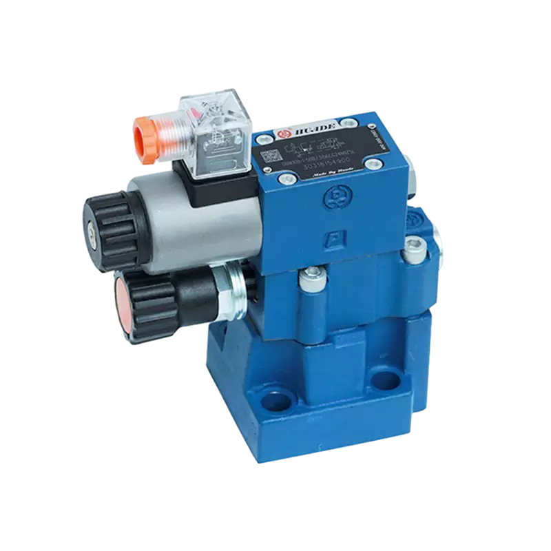
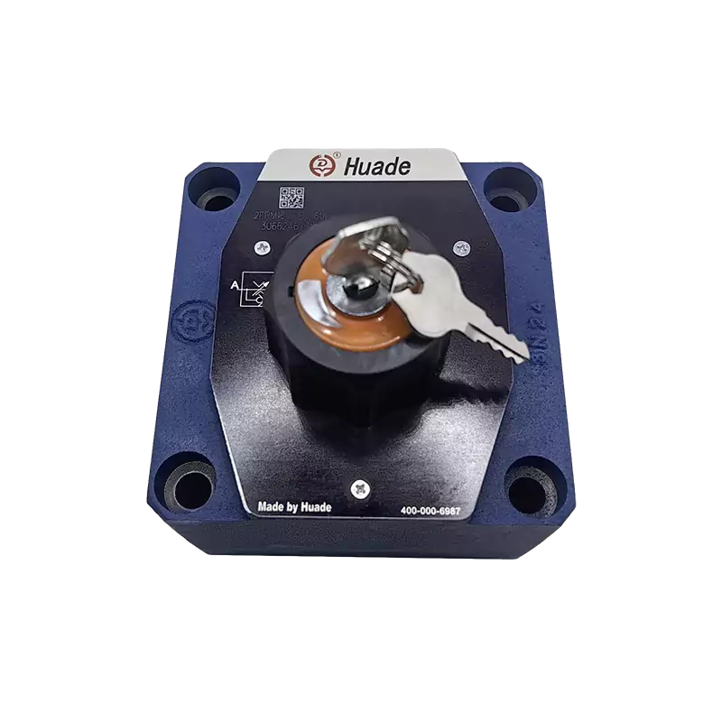
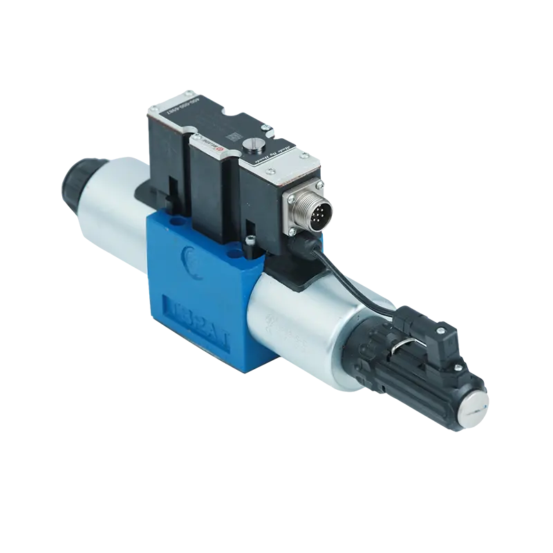
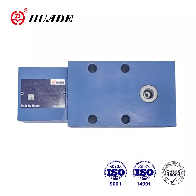
When you look at a hydraulic valve, you'll notice several port markings stamped or labeled on the valve body. The A and B designations identify the work ports, which are the two primary output connections that link the valve directly to your hydraulic actuator. These ports control the bidirectional flow of hydraulic fluid to and from a cylinder or motor, making them essential interfaces for converting fluid power into mechanical motion.
The A and B ports function as reversible connections in a hydraulic circuit. At any given moment, one port supplies pressurized fluid to extend or rotate the actuator, while the other port returns fluid back to the tank. When you shift the valve spool to change direction, the roles of A and B reverse, which is exactly how hydraulic cylinders extend and retract or how motors change rotation direction.
This port identification system follows international standards established by ISO 1219-1 and the North American NFPA standard ANSI B93.7. These standards ensure that engineers and technicians anywhere in the world can read hydraulic schematics and understand valve connections without confusion. The standardization of port nomenclature is critical for system interoperability, especially when you're working with components from different manufacturers or troubleshooting equipment in the field.
The Complete Hydraulic Valve Port System
To fully understand what A and B ports do, you need to see how they fit into the complete port structure of a directional control valve. A typical four-port valve configuration includes four main connections that work together to control actuator movement.
The P port serves as the pressure inlet, receiving high-pressure fluid from the hydraulic pump. This is where system pressure enters the valve. The T port (sometimes marked as R for remote return) is the tank return line where fluid flows back to the reservoir after completing work in the actuator. Some valves also include an L port for internal leakage drainage, which prevents pressure buildup in the valve's spring chamber and spool clearance areas.
``` [Image of 4 port directional control valve diagram] ```The A and B work ports connect directly to the two chambers of a double-acting cylinder or the two ports of a hydraulic motor. These are called work ports because they're where the actual energy conversion happens - where pressurized fluid becomes mechanical force and motion. Unlike the P and T ports which maintain relatively fixed roles, the A and B ports constantly swap between supply and return functions depending on the spool position.
| Port Designation | Standard Name | Primary Function | Typical Pressure Range |
|---|---|---|---|
| P | Pressure/Pump | Main pressure inlet from pump | 1000-3000 PSI (70-210 bar) |
| T (or R) | Tank/Return | Low-pressure return to reservoir | 0-50 PSI (0-3.5 bar) |
| A | Work Port A | Bidirectional actuator connection | 0-3000 PSI (variable) |
| B | Work Port B | Bidirectional actuator connection | 0-3000 PSI (variable) |
| L | Leakage/Drain | Internal leakage removal | 0-10 PSI (0-0.7 bar) |
How A and B Ports Control Actuator Direction
The fundamental job of A and B ports is to enable reversible motion control. When you understand how fluid paths change inside the valve, you'll see why these two ports are essential for bidirectional control.
In a typical double-acting hydraulic cylinder setup, port A commonly connects to the cap end (the side without the rod), while port B connects to the rod end. However, this connection pattern isn't mandatory and depends on your specific system design and the desired default motion direction. What matters is that you maintain consistency throughout your circuit design and documentation.
When the valve spool shifts to position one, the internal passages connect P to A and B to T. Pressurized fluid flows from the pump through the A port into the cylinder's cap end, pushing the piston and extending the rod. Simultaneously, fluid displaced from the rod end flows out through port B, through the valve's internal passages, and returns to tank through the T port. The pressure differential between the two cylinder chambers creates the force needed to move the load.
Shifting the spool to position two reverses these connections. Now P connects to B and A connects to T. Fluid flows into the rod end through port B, pulling the piston back and retracting the rod. The fluid displaced from the cap end exits through port A and returns to tank. This reversibility is the core principle that makes directional control valves work.
The flow rate through the A and B ports determines actuator speed. This flow rate depends on two factors: the pump output volume and the valve's internal orifice area created by the spool position. The basic orifice equation governs this relationship:
Where Q is flow rate, Cd is the discharge coefficient, Ao is the effective orifice area, ΔP is pressure differential, and ρ is fluid density. By precisely controlling the spool displacement, you control the effective orifice area and therefore the flow to each work port.
Center Position Configurations and Their Impact on A and B Ports
The behavior of A and B ports in the valve's neutral position significantly affects your system's performance characteristics. Different center configurations serve different operational needs, and understanding these variations helps you select the right valve for your application.
A closed-center valve configuration blocks all ports when the spool is in neutral position. Both A and B ports are sealed off from P and T. This design provides excellent load holding capability because the trapped fluid in the actuator chambers cannot escape, even under external load. The cylinder maintains its position with minimal drift. However, if you're using a fixed-displacement pump, you'll need a pressure relief valve or unloading circuit to prevent excessive pressure buildup when the valve is centered, since the pump continues delivering flow with nowhere to go.
Open-center valves take a different approach. In neutral position, P connects to T, and both A and B ports also connect to T. This configuration allows the pump to unload at low pressure during standby, dramatically reducing power consumption and heat generation. The system runs much cooler during idle periods. The tradeoff is that you lose load holding capability - if external forces act on your cylinder, it will drift because the ports connect to the low-pressure tank line.
Tandem-center valves represent a middle ground. The P port blocks in neutral, but A and B connect to T. This design works well in series circuits where you want to unload the current actuator while allowing flow to continue to the next valve in the circuit. The actuators connected to A and B ports relieve pressure, but the pump doesn't necessarily unload unless all valves in the series are centered.
Some specialized valves use regeneration-center configurations where A and B ports internally connect to each other in certain positions. This cross-porting enables advanced flow management techniques that can significantly increase actuator speed by allowing fluid from one chamber to supplement pump flow to the other chamber.
| Center Type | A and B Port Status | Load Holding | Energy Efficiency | Best Applications |
|---|---|---|---|---|
| Closed Center | Blocked | Excellent | Requires unloading circuit | Precision positioning, variable pumps |
| Open Center | Connected to T | Poor | Excellent (pump unloads) | Low-duty cycle, mobile equipment |
| Tandem Center | Connected to T | Poor | Good (in series circuits) | Multiple actuator systems |
| Regeneration Center | Cross-connected (A to B) | Fair | Excellent (flow summation) | High-speed extending, excavators |
A and B Ports in Real-World Applications
Understanding port theory is important, but seeing how A and B ports function in actual equipment helps solidify the concepts. Different types of hydraulic actuators use these ports in specific ways that match their operational requirements.
In double-acting cylinders, which represent the most common application, the A and B port connections determine the cylinder's motion pattern. Consider a typical hydraulic press where you need controlled extension and retraction. Port A connects to the blind end with the larger piston area, while port B connects to the rod end with smaller effective area due to the rod volume. When you send flow through port A, the full piston area generates force for the pressing operation. During retraction, flow through port B moves the smaller effective area, and because flow rate equals area times velocity, the cylinder retracts faster than it extends for the same flow rate.
Hydraulic motors use A and B ports to control rotation direction. In a bidirectional motor application like a rotary drill or conveyor drive, the port receiving pressure determines which way the motor shaft turns. Switching pressure from port A to port B reverses the rotation instantly. The pressure differential between the two ports creates the torque, while the flow rate determines rotational speed. If your motor specification shows 10 cubic inches per revolution displacement and you're flowing 20 GPM, you can calculate that you'll get 231 RPM (using the conversion that 1 GPM equals 231 cubic inches per minute).
Advanced mobile equipment like excavators demonstrate sophisticated use of A and B port management. The boom cylinder in an excavator experiences varying load conditions - sometimes lifting against gravity, sometimes being pushed down by gravity. The control system monitors pressure signals from the A and B ports continuously. During boom lowering with a loaded bucket, the rod-end chamber (typically port B) might show higher pressure than the pump supply because gravity is driving the motion. Smart control systems detect this condition and can activate regeneration circuits or energy recovery systems, using the A and B port pressure differentials as key feedback signals.
Proportional Control and Load-Sensing Through A and B Ports
Modern hydraulic systems have evolved far beyond simple on-off valve control. Proportional and servo valves enable precise, continuous control of flow through the A and B ports, and these ports also serve as crucial sensor points for advanced control strategies.
Proportional valves modulate spool position based on an electrical input signal, typically a current between 0 and 800 milliamps or a voltage signal. As the current increases, the spool gradually shifts further from neutral, progressively opening the flow paths between P and the work ports. This variable orifice area gives you smooth, controlled acceleration and deceleration of your actuator. An operator using a joystick to control an excavator boom isn't switching a valve on and off - they're sending proportional commands that translate into precise flow rates through ports A and B.
Load-sensing (LS) systems take this sophistication further by using pressure feedback from the A and B ports to optimize system efficiency. In an LS system, a small pilot line connects from the highest-pressure work port back to the pump's displacement control or to a pressure compensator on the valve. The system continuously measures which work port (A or B) currently faces the highest load pressure, designated as PLS. The pump or compensator adjusts to maintain a constant pressure margin above this load pressure, typically 200-300 PSI. The relationship is expressed as:
This load-sensing approach means your pump only generates enough pressure to overcome the actual load plus a small margin for control. Instead of running at full system relief pressure all the time and wasting energy through throttling, the system matches pressure to demand. When you're moving an unloaded cylinder quickly, the A and B port pressures remain low, and so does pump pressure. When you encounter heavy resistance, the work port pressure rises, the LS signal increases, and the pump automatically increases its output pressure. This real-time pressure matching based on A and B port feedback can reduce system energy consumption by 30 to 60 percent compared to fixed-pressure systems.
Independent metering valve (IMV) technology represents the cutting edge of work port control. Traditional directional valves mechanically couple the meter-in flow (P to A or P to B) with the meter-out flow (A to T or B to T) through a single spool position. IMV systems use separate electronically controlled valves for all four flow paths: P to A, P to B, A to T, and B to T. This decoupling allows the control system to independently optimize supply and return flows based on load conditions, motion requirements, and energy efficiency targets. The controller can analyze pressure and flow data from the A and B ports in real time and adjust each valve element independently, enabling functions like automatic regeneration, differential control, and load-compensated motion profiling.
Hydraulic Regeneration: Advanced A and B Port Management
Regeneration circuits demonstrate one of the most sophisticated applications of A and B port control, commonly found in construction and agricultural equipment. Understanding regeneration helps you appreciate how these seemingly simple work ports enable complex energy management.
Hydraulic regeneration exploits the area difference between a cylinder's cap end and rod end. When a differential cylinder extends, the cap end (typically port A) requires more fluid volume than the rod end (typically port B) expels, because the rod occupies space in the rod-end chamber. The volume relationship is:
In a regeneration circuit, instead of sending the rod-end return flow through port B to tank where it would dissipate energy through throttling, the system redirects this return flow to merge with pump flow supplying the cap end through port A. This flow summation significantly increases extension speed. If your pump supplies 20 GPM and the rod end can supply an additional 8 GPM through regeneration, your cap end receives 28 GPM total, boosting speed by 40 percent.
The circuit implementation requires careful management of the A and B port paths. A regeneration valve (sometimes called a makeup valve or regeneration spool) controls the connection between ports. When the system determines that regeneration is beneficial - typically when gravity or external forces assist motion - the regeneration valve activates. It blocks the path from port B to tank and instead connects port B to port A. A check valve in this regeneration line prevents backflow when port A pressure exceeds port B pressure, which happens during powered extension against a load.
The control system makes the regeneration decision based on pressure signals from the work ports. During boom lowering on an excavator, sensors detect that the rod-end pressure at port B is elevated because gravity is pushing down. This pressure signal indicates that the rod-end fluid contains recoverable energy. The controller activates regeneration, directing this high-pressure return flow to supplement pump supply rather than waste it through a throttling valve. This approach simultaneously increases speed and reduces energy waste, addressing two performance goals with one control strategy.
Modern electrohydraulic systems integrate regeneration control directly into the main valve logic. Some advanced mobile valves feature built-in regeneration passages that activate based on pressure-compensated spool positions, eliminating the need for separate regeneration valves. IMV systems can implement regeneration entirely through software, instantly reconfiguring flow paths by adjusting individual valve elements without any mechanical regeneration components.
Diagnostics and Maintenance Considerations for Work Ports
The A and B ports serve as excellent diagnostic access points for troubleshooting hydraulic system problems. Understanding what to measure at these ports and how to interpret the results is essential for effective maintenance.
When diagnosing slow actuator speed, connect pressure gauges to both A and B ports during operation. Compare the working pressure at the active port (the one receiving pump flow) against the expected load pressure. If port A should show 1500 PSI to lift a known load but you're seeing 2200 PSI, you have excessive resistance somewhere. This could indicate a restricted line between the valve and cylinder, internal cylinder seal wear causing bypass, or a partially clogged filter in the return line increasing back pressure at port B.
Pressure imbalance between the work ports during motion can reveal valve or cylinder problems. When extending a cylinder, port A should show load pressure plus the pressure drop across the return-side restriction, while port B should show only the back pressure from return line resistance (typically under 100 PSI). If port B shows abnormally high pressure during extension, you might have a restriction in the B-to-T flow path - possibly a clogged valve passage or kinked return hose. This back pressure reduces the pressure differential across the cylinder, decreasing the available force and speed.
Pressure ripple or instability at the A and B ports often indicates contamination affecting valve spool movement. If particle contamination exceeds ISO 4406 cleanliness level 19/17/14, silt accumulation can cause erratic spool motion, resulting in pressure fluctuations visible at the work ports. This condition requires immediate attention because it degrades control precision and accelerates component wear.
Cross-port leakage represents another common failure mode you can detect through work port testing. Block both actuator ports and pressurize one side through port A while monitoring port B pressure. In a closed-center valve with good spool fit, pressure on the blocked port B should remain below 50 PSI when port A sees system pressure. Rapid pressure rise on port B indicates excessive internal leakage across the spool lands, meaning the valve needs spool replacement or complete overhaul.
| Symptom | Port A Reading | Port B Reading | Likely Cause | Action Required |
|---|---|---|---|---|
| Slow extension | Excessive pressure | Normal (low) | A-port line restriction or cylinder seal failure | Check lines, inspect cylinder seals |
| Slow retraction | Normal (low) | Excessive pressure | B-port line restriction or return blockage | Check lines, clean valve passages |
| Cylinder drift | Pressure decay | Pressure decay | Internal valve leakage or cylinder seal failure | Perform cross-port leakage test |
| Erratic motion | Pressure oscillation | Pressure oscillation | Contamination affecting spool or cavitation | Check fluid cleanliness, inspect for air |
| No motion | Low pressure | High pressure | Reversed hose connections at actuator | Verify plumbing against schematic |
Protection devices at the A and B ports safeguard your system from damage during abnormal conditions. Cross-port relief valves installed between the work ports prevent pressure spikes when the cylinder encounters sudden mechanical stops or impact loads. These valves typically set 10 to 20 percent above normal maximum working pressure. When port A pressure exceeds the relief setting, the valve opens and connects port A to port B, allowing fluid to bypass the blocked cylinder instead of generating destructive pressure peaks that could rupture hoses or damage seals.
Makeup valves protect against cavitation during overrunning loads. If a heavy mass drives the cylinder faster than the pump can supply flow, the supply-side chamber develops negative pressure. A makeup valve opens when this vacuum reaches about 5 PSI below atmospheric, allowing low-pressure fluid from tank to flow into the starved chamber through the work port. This prevents the formation of vapor bubbles that would cause noise, vibration, and erosive damage to internal surfaces.
Conclusion: The Central Role of A and B Work Ports
The A and B ports on a hydraulic valve represent far more than simple connection points. These work ports form the critical interface where hydraulic control translates into mechanical action, where system intelligence meets actuator reality, and where energy efficiency strategies succeed or fail. While their basic function remains constant across applications - providing reversible flow paths to control actuator direction and speed - their implementation in modern systems demonstrates remarkable sophistication.
From basic directional control in a simple cylinder circuit to complex regeneration systems in construction equipment, the management of flow and pressure through the A and B ports determines system performance. Load-sensing systems rely on pressure signals from these ports to optimize energy use. Regeneration circuits reconfigure the paths between A and B to recover energy and boost speed. Proportional control systems modulate flow through these ports with precision measured in milliseconds. Independent metering technology has evolved to give unprecedented control authority over each work port's supply and return paths.
As hydraulic technology continues advancing toward greater electrification and digital control, the physical A and B ports remain fundamentally important. What changes is how we manage them - with faster valves, smarter algorithms, and more sophisticated feedback loops. Whether you're maintaining a decades-old mobile machine or designing a cutting-edge servo-hydraulic system, understanding what the A and B ports are and how they function provides the foundation for effective hydraulic system work.


