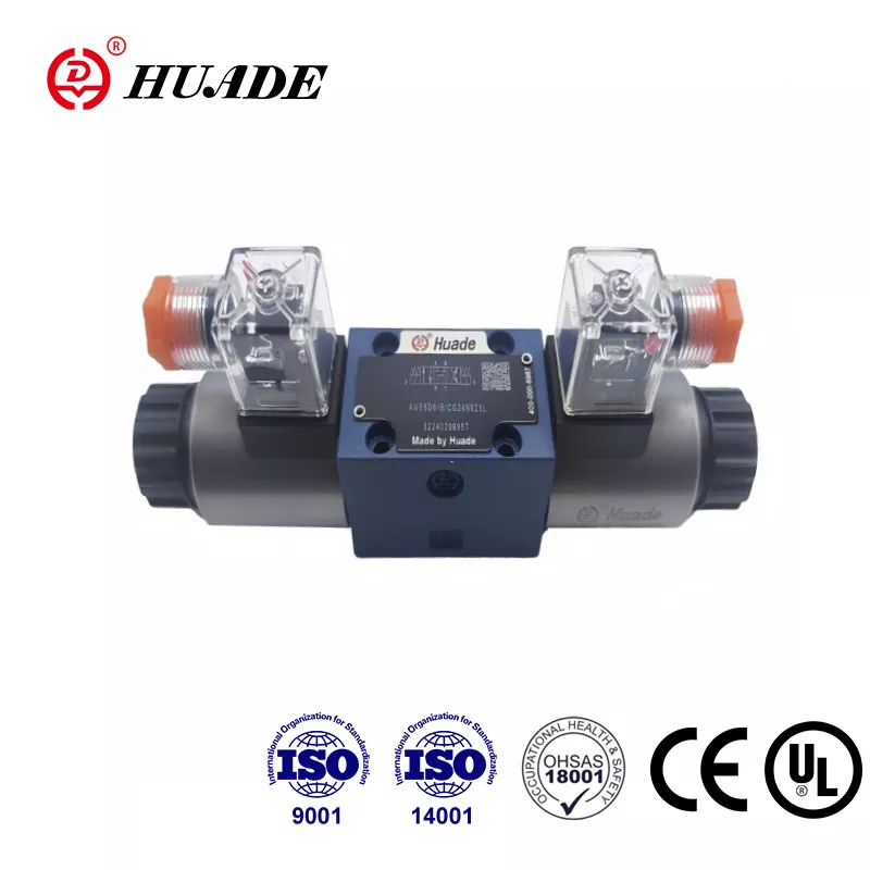
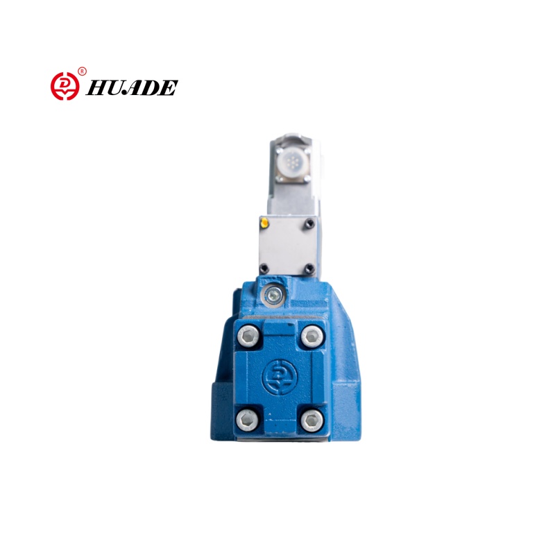
Selecting the right hydraulic valve can make or break your fluid power system. If you've ever stood in front of a valve catalog wondering whether you need a 2-way or 3-way valve, you're not alone. These two valve types serve fundamentally different purposes in hydraulic circuits, and understanding their differences will save you time, money, and potential system failures.
The basic answer is straightforward: a 2-way valve has two ports and controls whether fluid flows or stops (on/off function), while a 3-way valve has three ports and controls where fluid flows (directional function). But this simple distinction hides important engineering details that determine which valve belongs in your application.
Understanding Directional Control Valves in Hydraulic Systems
Directional control valves function as the logic controllers of hydraulic systems. They determine when hydraulic oil starts moving, when it stops, and which path it takes through the circuit. Engineers often call these components switching valves because they change the state of fluid flow paths.
The hydraulic industry uses a standardized naming system based on ISO standards. You'll see valves labeled with an X/Y format, where X represents the number of working ports and Y represents the number of positions. For example, a 4/3 valve has four working ports and three positions. This notation system excludes control ports like pilot signal connections, counting only the ports that handle main fluid flow.
The position count (Y) defines how many stable flow connection patterns the valve can provide. A simple 2/2 valve offers basic on/off control. A 3/2 valve introduces fluid diversion capability. The widely used 4/3 valve manages double-acting cylinders with a dedicated center position. As you move from 2/2 to 3/2 to 4/3, you're adding layers of control complexity that match increasingly sophisticated system requirements.
2-Way Hydraulic Valves: Isolation and Linear Flow Control
A 2-way valve operates as a simple fluid gate. Picture a door that opens or closes to allow or block flow through a single pathway. This valve has one inlet connection and one outlet connection, creating a straight-through flow path when open and a complete blockage when closed.
Most 2-way valves use solenoid actuation for electromechanical control. The moving element (typically a poppet or spool) shifts between two positions: fully open or fully closed. There's no middle ground in basic 2-way valve operation.
The default state of a 2-way valve matters significantly for system safety. Normally closed (NC) valves block flow when de-energized, requiring power to open. This configuration dominates safety-critical isolation applications. If electrical power fails, an NC valve automatically closes, preventing uncontrolled fluid flow or unexpected actuator movement. This fail-safe characteristic makes NC valves the default choice for isolation points.
Normally open (NO) valves work oppositely, allowing flow when de-energized and requiring power to close. Engineers select NO valves less frequently, typically in applications where maintaining flow during power loss is the safer condition.
The primary applications for 2-way valves include isolation, dumping, metering, and mixing functions. A special case is the check valve, which is essentially a 2/2 valve passively driven by line pressure. Check valves allow free flow in one direction while blocking reverse flow, protecting pumps and maintaining pressure in specific circuit branches.
When selecting a 2-way valve, engineers focus on maximum flow rate (measured in gallons per minute or liters per minute) and maximum working pressure (measured in PSI or bar). Because these valves often handle isolation at high flow rates, minimizing pressure drop across the open valve is critical. This requirement drives many 2-way designs toward poppet construction, which provides the largest internal flow area with minimal restriction.
However, 2-way valves have an inherent limitation: they cannot manage fluid return to tank without external help. If you use a 2-way valve to control a single-acting cylinder, you must add a separate relief or drain valve to exhaust fluid. This limitation makes the 3-way valve a more integrated solution for actuator control.
3-Way Hydraulic Valves: Directional Control and Actuator Management
Adding a third port transforms a valve from a simple gate into a traffic controller. A 3-way valve features three specialized ports: pressure (P), work (A), and tank (T). The ISO naming convention identifies these valves as 3/2 (three ports, two positions), meaning the valve provides two distinct flow connection patterns.
The fundamental advantage of 3-way valves lies in managing fluid destination. These valves perform three critical functions: diverting (routing a single input to one of two destinations), selecting (choosing between two pressurized inputs to supply a single downstream system), and mixing (combining two fluid inputs into one combined output stream).
The most common application for 3/2 directional control valves is managing single-acting hydraulic cylinders. These cylinders rely on hydraulic pressure to extend in one direction and use an internal spring or external load to retract. The 3-way valve coordinates both actions through its two positions.
In the extend position, the valve spool shifts to connect P to A while isolating T. Pressure builds in the cylinder chamber, overcoming the spring or load force to move the piston outward. When the valve returns to its reset position (typically spring-returned), it connects A to T while isolating P. The cylinder chamber pressure exhausts through the T port to tank, allowing the spring or load potential energy to push the piston back while displacing fluid to tank.
This integrated supply and exhaust control is what separates a 3-way valve from two separate 2-way valves in series. The reliable activation of the A-to-T path in the valve's reset position is the decisive functional requirement. Without this exhaust path, the retraction mechanism cannot function, regardless of spring force. The 3-way valve ensures the actuator can safely and quickly return to its initial position under all conditions.
While high-pressure directional control valves typically use spool construction, 3-way functionality can also be achieved through L-port or T-port rotary designs. These structures are specifically suited for managing mixing and diverting behavior in fluid paths.
From a system perspective, a 3-way valve combines the functions of two separate 2/2 isolation valves into one component, managing both fluid supply and return through a single control signal. This structural integration improves cost-effectiveness and simplifies plumbing compared to using multiple 2-way valves for diversion or single-acting control.
Direct Comparison: Key Differences Between 2-Way and 3-Way Valves
The distinction between these valve types extends beyond port count to fundamental differences in control topology and fluid management capability.
| Characteristic | 2-Way Valve (2/2) | 3-Way Valve (3/2) |
|---|---|---|
| Core Function | ON/OFF isolation; start/stop flow control | Diversion, selection, mixing; actuator control |
| Number of Ports | 2 (generic inlet P₁ / outlet P₂) | 3 (pressure P, work A, tank T) |
| Control Type | Flow existence control (Is fluid flowing?) | Flow direction control (Where is fluid going?) |
| Standard Application | Line isolation, tank filling/draining, metering | Single-acting cylinders (spring return) |
| Fluid Management | Unidirectional linear flow control | Active fluid redirection and path selection |
| Fail-Safe Mechanism | Typically normally closed (NC) shutoff | Depends on actuator (A→T path usually spring-reset default) |
| System Complexity | Simple, fewer components | Higher integration, replaces multiple 2-way valves |
| Cost | Lower initial cost | Higher cost but better value for diversion applications |
| Installation | Simpler installation | More complex plumbing requirements |
| Pressure Drop | Generally lower when open | May be higher due to internal flow path complexity |
The dedicated tank (T) port on 3-way valves is essential for necessary fluid decompression. Without this return path, spring-return cylinders cannot function. Meanwhile, 2-way valves excel at their simpler role: creating or eliminating a flow path with minimal pressure loss and maximum sealing integrity.
For applications requiring fluid redirection such as bypass circuits or actuator control, a single 3-way valve typically offers superior economics and space efficiency compared to using two or more 2-way isolation valves. Some multi-purpose 3-way valves can even function temporarily as 2-way valves by plugging the unused third port, which simplifies spare parts inventory and maintenance logistics.
The ISO 1219-1 standard provides universal symbols for fluid power systems. The graphic symbols immediately communicate functional differences. A 2/2 symbol shows either a straight line (open) or a blocked line (closed). A 3/2 symbol must display two complete internal flow path diagrams within its two position boxes, confirming its redirection capability with paths like P→A and A→T visible.
Whether 2/2 or 3/2, actuator symbols (spring return, solenoid control, lever operation) attach to the sides of position boxes to indicate activation method. For 3-way valves, the specific designation of P, A, and T ports is mandatory in fluid power engineering. Reversing the P and T connections could damage the pump or overpressurize the tank, highlighting the critical directional specificity in 3-way design. In contrast, because 2-way valves perform isolation, their P₁ and P₂ ports are typically universal, and flow reversal is usually permissible or irrelevant to the shutoff function.
Valve Internal Structures: Poppet versus Spool Design
The physical construction of a valve (poppet or spool) determines its performance characteristics including leakage, speed, and pressure holding capability. Different structures are better suited to either 2-way or 3-way functions.
Poppet valves rely on a sealing element (disc or cone) pressing tightly against a valve seat to form a nearly perfect barrier. This construction provides excellent sealing integrity, making poppet valves ideal for applications requiring pressure holding or absolute isolation. Internal leakage rates in poppet valves are extremely low. The short stroke and minimal fluid obstruction give poppet valves fast response times and the ability to handle high flow rates.
Poppet designs typically provide closed crossover, meaning during switching there is no momentary interaction or simultaneous opening between fluid paths. This characteristic is critical for applications demanding precise control. However, poppet valves are usually unbalanced. Inlet pressure assists the seal, but if supply pressure is removed, downstream pressure might cause the valve to open. This makes poppet valves unsuitable for applications requiring long-term maintenance of downstream pressure. Additionally, because they must overcome spring tension and fluid pressure, poppet valves typically require higher actuation force to initiate movement.
Spool valves consist of a shaft with multiple sealing lands (pistons) that move axially within a valve body. Sealing relies on precise manufacturing tolerances and dynamic seals such as O-rings. Spool construction is inherently designed to manage multiple connections simultaneously, making it the structural requirement for implementing 3-way (P, A, T) and more complex 4/3 or 5/2 system functions.
Spool valves provide consistent response times and are better suited than poppet valves for maintaining downstream pressure. However, due to the need to simultaneously manage connections and isolations between multiple ports, spool valves have inherent internal leakage at the spool lands (small amounts of fluid passing between the spool plunger and body bore). Compared to the positive sealing of poppet valves, spool valves typically have higher internal leakage rates.
The higher internal leakage rate of spool valves means the pump must work continuously to maintain pressure, wasting energy and generating excess heat in the tank. For simple applications requiring long-term isolation (2-way function), the superior leak-free closure of poppet valves is a significant energy efficiency advantage. Poppet valves require higher actuation force to overcome pressure differential that assists sealing, while spool designs used in 3-way and 4/3 systems typically incorporate pressure balancing features to minimize switching force required, ensuring consistent performance regardless of system pressure fluctuations.
| Design Parameter | Poppet Structure (favors 2/2) | Spool Structure (favors 3/2 and above) |
|---|---|---|
| Flow Complexity | Simple, linear control | Complex, multi-path management |
| Internal Leakage Rate | Very low (excellent sealing) | Higher (dynamic plunger seals) |
| Dynamic Response | Fast (short stroke) | Consistent (predictable stroke) |
| Transition State | Closed crossover (ensures precision) | Open crossover (required for fluid transfer) |
| Actuation Force | High (must overcome pressure-assist) | Moderate/balanced (better consistency) |
Low leakage is critical for the isolation role of 2-way valves. Poppet valves are better suited for sudden, critical shutoff functions. The 3-way system requires a brief transition state to manage fluid transfer between ports, which spool designs naturally accommodate. High actuation force works for dedicated 2-way isolation but is unsuitable for complex directional control. Spool design enables alignment of three independent ports (P, A, T) in two states within a single element.
Selecting the Right Valve: Application Guidelines
Choosing the optimal valve requires evaluating factors beyond just port and position count. Engineers must assess maximum flow rate, maximum working pressure, fluid path requirements, and actuation method.
Pay attention to pressure limitations, which often differ across ports. For example, the return (T) port pressure rating is typically far lower than work (A/B) or pressure (P) ports. In one manufacturer's specification, the P port maximum operating pressure is 3,625 PSI while the T port maximum is only 725 PSI. Ignoring these differences can cause system failure or create hazardous conditions.
Proper system integration relies on standardized port connections such as SAE O-ring ports to ensure robust, leak-free seals and prevent blockages. Use standard port nomenclature consistently: P for pressure supply, T for tank return, and A/B for work ports connecting to actuators.
Choose 2-way valves (preferably poppet construction) for critical isolation points, safety shutoff functions, or when extremely low internal leakage and fast response time are non-negotiable requirements. The 2-way valve is a fundamental linear flow control element whose advantage lies in simplicity, reliability, and strong sealing.
Choose 3-way valves (preferably spool construction) for controlling single-acting hydraulic actuators, diverting fluid paths, or systems requiring selection/mixing of input flows. The integrated P-A-T control function is a core requirement for actuator management, providing a compact, economical, and functionally complete solution.
The roles of 2/2 and 3/2 valves in hydraulic systems are distinct and non-interchangeable. The difference between them is not merely one additional port, but rather the system logic and fluid management complexity they handle. Understanding these fundamental differences ensures you specify the right valve for your application, avoiding costly redesigns and system performance problems.


