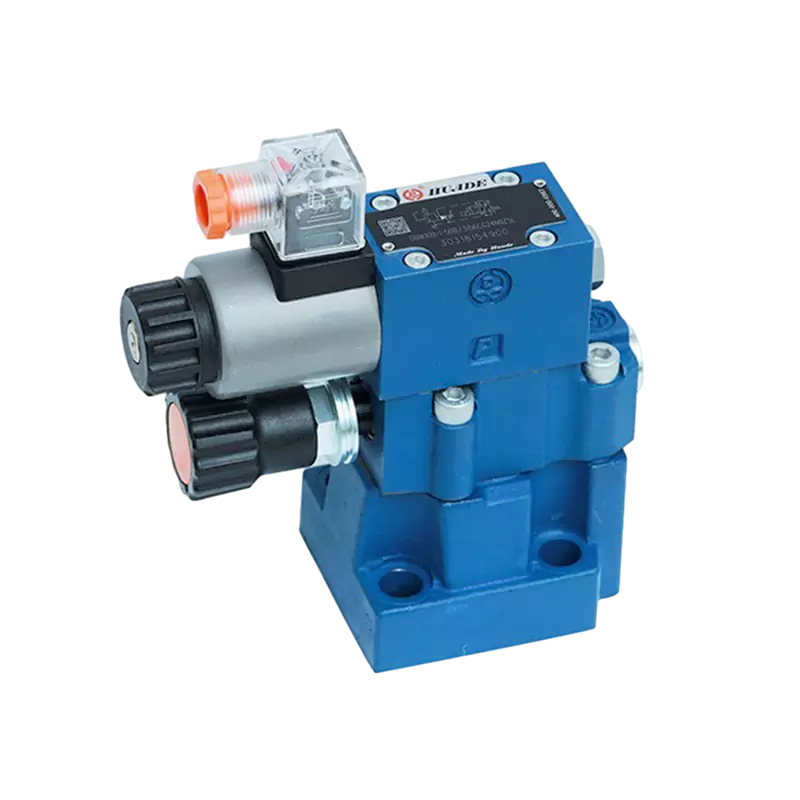
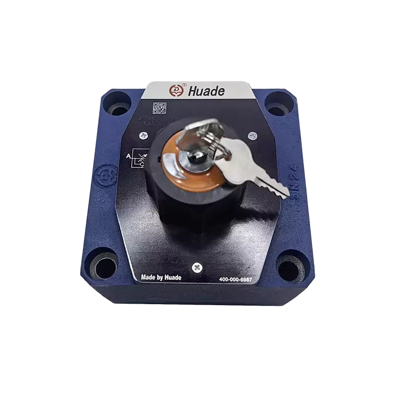
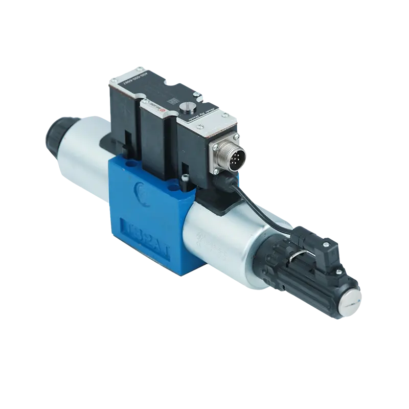
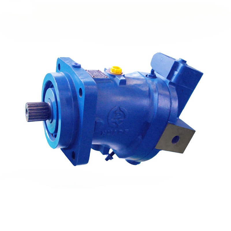
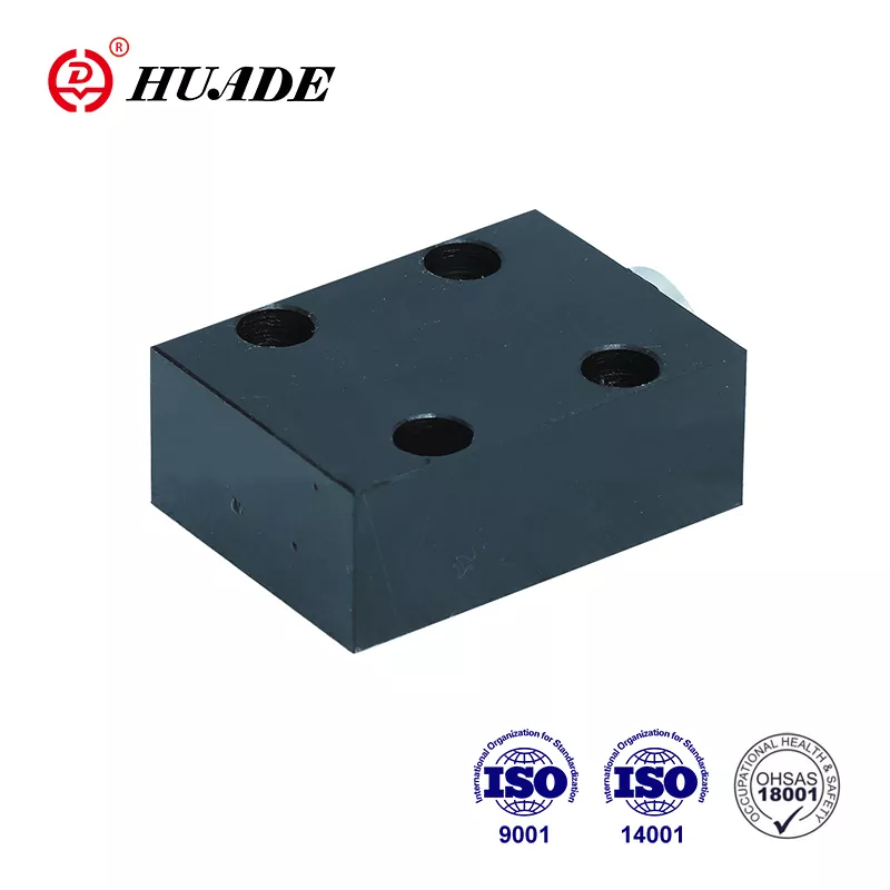
Hydraulic check valves serve as fundamental safety components in fluid power systems. These mechanical devices automatically control fluid flow direction without requiring external control signals or manual intervention. In hydraulic circuits, they prevent backflow that could damage pumps, cause uncontrolled actuator movement, or create dangerous pressure conditions.
What is a Hydraulic Check Valve
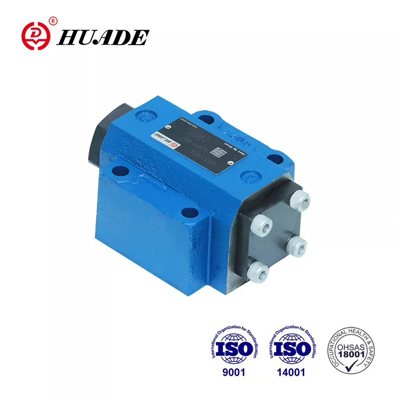
A hydraulic check valve, also known as a non-return valve (NRV), is a mechanical device designed to allow hydraulic fluid to flow in one predetermined direction while blocking any reverse flow. The valve operates passively through fluid pressure differential. When forward pressure exceeds the valve's cracking pressure threshold, the internal check element lifts from its seat, allowing fluid passage. When inlet pressure drops or reverse flow attempts to occur, the check element returns to its closed position, creating a seal that prevents backflow.
The basic construction includes several key components. The valve body houses the internal mechanism and provides connection ports. The poppet or ball serves as the movable check element that either permits or restricts flow. A spring mechanism maintains closure bias, keeping the check element pressed against its seat when flow stops or reverses. The valve seat provides the sealing surface where the check element creates a tight seal to block reverse flow.
This simple yet critical function protects system integrity in multiple ways. Unintended backflow in hydraulic systems can cause cavitation damage to pumps, permit uncontrolled descent of loads under gravity, or allow pressure spikes to propagate through the circuit. Engineering specifications for hydraulic check valves must prioritize reliability, material strength, and resistance to pressure transients.
How Hydraulic Check Valves Work
The operating principle centers on pressure differential and spring force balance. In the closed state, spring preload holds the check element firmly against its seat. The spring force plus any back pressure on the outlet side creates the cracking pressure requirement.
When inlet pressure rises and exceeds the cracking pressure, hydraulic force overcomes spring resistance. The check element lifts off its seat, opening a flow path. Flow area increases as the element moves further from the seat, reducing pressure drop across the valve. The valve reaches full open position when flow velocity and pressure differential are sufficient to completely compress the spring.
During flow reversal attempts, outlet pressure exceeds inlet pressure. This pressure differential immediately forces the check element back toward its seat. The spring assists this closure movement. Once seated, the check element creates a mechanical seal. Higher reverse pressure actually improves sealing force, as the pressure acts on the element's sealing surface area, pushing it more firmly against the seat.
The automatic operation requires no electrical signals, pilot pressure, or operator input. This passive functionality makes hydraulic check valves inherently reliable for safety-critical applications. However, the mechanical simplicity also means the valve cannot provide variable flow control or modulation capabilities.
Types of Hydraulic Check Valves
Direct-Acting Check Valves
Direct-acting configurations use a simple mechanical linkage between fluid pressure and the check element. These valves respond quickly to pressure changes because the check element directly experiences system pressure without intermediate control stages.
The poppet-style direct-acting valve uses a conical or flat-bottomed poppet as the check element. This geometry provides uniform pressure distribution when closed, which improves sealing stability at high pressures. Modern poppet designs using high-strength steel offer superior wear resistance and corrosion resistance compared to traditional ball check valves. The flat seating surface of the poppet creates more reliable sealing integrity, particularly in applications involving hazardous fluids or extreme pressure conditions.
Ball-style check valves use a free-moving sphere as the closure element. The spherical geometry allows the ball to self-center and adjust to its seat. However, at high pressures, the ball's roundness creates uneven pressure distribution that can compromise seal integrity. This design limitation makes ball check valves less suitable for critical applications where leak-tight sealing is mandatory. The engineering trade-off favors poppet designs when sealing reliability outweighs concerns about cost or manufacturing simplicity.
Direct-acting valves typically serve smaller systems with stable pressure and flow requirements. Their simplicity translates to lower initial cost and easier maintenance. However, their flow capacity and pressure precision remain limited compared to pilot-operated alternatives.
Pilot-Operated Check Valves (POCV)
Pilot-operated check valves incorporate an additional pilot port connected to a control circuit. This design uses a small amount of hydraulic fluid to control main valve opening and closing through pressure differential. The pilot pressure acts on a dedicated area of the check element, providing the force needed to open the valve against spring pressure and any back pressure.
The complexity of POCV design results in higher initial cost and maintenance requirements. However, these valves handle higher flow rates and pressures while providing superior pressure accuracy. The pilot control mechanism allows precise timing of valve actuation synchronized with other system functions.
POCVs excel in load-holding applications requiring near-zero leakage. They effectively prevent cylinder drift from slow system leakage or maintain position during hydraulic hose failure scenarios. The tight sealing characteristics make POCVs economical solutions for static load holding where position must be maintained without active power consumption.
The critical limitation of POCVs lies in dynamic control capability. Unlike counterbalance valves, POCVs lack flow metering ability. When applied to gravity-driven overrunning load conditions that require controlled lowering, POCVs can cause severe ratcheting motion in cylinders. This produces massive hydraulic shock and vibration that damages system components. For applications requiring smooth, controlled load lowering, counterbalance valves with integral flow metering represent the only viable engineering solution, despite higher cost.
| Feature | Direct-Acting (Poppet/Ball) | Pilot-Operated Check Valve | Shuttle Valve (3-Way) |
|---|---|---|---|
| Operating Principle | Pressure differential directly drives element open/closed | Requires secondary pilot pressure signal to open reverse flow | Directs higher pressure from two supply lines to return line |
| Flow Capacity | Low to Medium | High | Low to Medium |
| Leakage Rate | Variable (soft seals tighter) | Near-zero in load holding | Low |
| Complexity/Cost | Simple, Lower Cost | Complex, Higher Cost | Simple |
| Response Time | Fast | Moderate | Fast |
Specialized Configurations
Shuttle valves represent a specialized three-way check valve configuration. These valves route the higher pressure fluid from two supply lines toward a common return line. The internal shuttle element moves based on pressure differential between the two inlets, automatically selecting and directing the higher pressure source.
``` [Image of hydraulic shuttle valve working flow diagram] ```Integrated designs have evolved to meet demands for compact, modular hydraulic systems. Cartridge-style check valves insert into manifold blocks with fluid paths integrated within the manifold body. This approach enables highly customized and space-efficient system layouts. Subplate mounting provides an alternative where the check valve connects to a subplate that supplies fluid passages. Subplate configurations allow rapid valve replacement or servicing without disturbing main piping systems.
Some designs incorporate flow control functionality through throttling orifices machined into the check element. This allows controlled fluid leakage in the normally blocked direction, transforming the check valve into a combination device providing both directional control and flow regulation.
Key Performance Parameters for Selection
Cracking Pressure Mechanics
Cracking pressure defines the minimum inlet pressure required to overcome internal spring force and open the valve for fluid flow. This parameter fundamentally controls valve responsiveness and actuation timing within hydraulic circuits. When inlet pressure exceeds the cracking pressure threshold, the check element lifts and fluid begins passing through the valve.
Spring force primarily determines cracking pressure magnitude. The spring rate and preload compression establish the force that inlet pressure must overcome. Some designs achieve zero cracking pressure through free-floating seals, but many applications intentionally specify higher cracking pressure for dynamic stability.
Higher cracking pressure prevents unintended valve opening from external shocks, vibration, or gravitational forces acting on the check element. In circuits subject to mechanical vibration or where back pressure fluctuates, elevated cracking pressure ensures the valve remains closed until deliberate flow is initiated. However, this stability improvement creates an engineering trade-off with energy efficiency.
The relationship between cracking pressure and system efficiency directly impacts operating cost. Higher cracking pressure valves produce greater pressure drop during flow, which translates to continuous energy loss. This sustained pressure loss reduces fluid transmission efficiency and increases system heat generation. From a life cycle cost (LCC) perspective, minimizing pressure drop improves efficiency and delivers environmental benefits through reduced power consumption. Designers must balance dynamic stability requirements against thermodynamic efficiency based on specific application sensitivity to vibration versus energy consumption.
Pressure Ratings and Safety Margins
Four critical pressure specifications govern hydraulic check valve selection and ensure equipment safety. Operating pressure defines the continuous, steady-state pressure range for normal valve function. System pressure represents the maximum transient or peak pressure the valve must withstand during operation.
Proof pressure serves as a structural integrity test parameter. Manufacturers pressure test valves to 1.5 times their rated pressure and hold for a specified duration, verifying no permanent deformation occurs under high stress. This testing follows ISO 10771 or API 6D standards to validate structural stability and leak-tight performance.
Burst pressure indicates the ultimate pressure at which valve structural failure is predicted. This rating incorporates appropriate safety factors above operating conditions. Rigorous adherence to these pressure definitions ensures structural integrity and compliance with safety margins required by industrial standards.
Flow Dynamics and Pressure Drop
Efficient hydraulic system operation depends on precise and consistent fluid flow delivery. However, internal valve geometry and operational mechanics create pressure drop (head loss) as fluid passes through the check valve. This energy dissipation represents lost system efficiency.
Pressure drop correlates directly with cracking pressure. Valves requiring higher cracking pressure produce increased head loss during flow. The continuous pressure loss diminishes fluid transmission efficiency and raises system energy consumption. Over extended operational periods, optimizing design to minimize head loss improves fluid transmission efficiency, yielding environmental benefits and reducing valve life cycle cost.
For applications sensitive to LCC considerations, designers should select valves engineered for lower pressure drop characteristics. The inherent design trade-off between dynamic stability and thermodynamic efficiency requires careful evaluation of actual application requirements, including system sensitivity to vibration versus energy consumption priorities.
Leakage Management Standards
Valve leakage separates into two categories with distinct consequences. External leakage involves fluid escaping from the valve body or connection joints. This causes working fluid loss, environmental contamination risk, and potential safety hazards in systems handling hazardous fluids.
Internal leakage occurs through the closed check element, between the poppet or ball and its seat. In load-holding applications, internal leakage produces cylinder drift, causing gradual loss of position control. Critical safety systems require stringent leakage control standards. Manufacturers minimize leakage rates through appropriate seal material selection and precision machining of sealing surfaces.
Seal Material Engineering Trade-offs
Seal material selection determines performance envelope and application suitability. Soft seal materials including elastomers like Viton or thermoplastics such as PTFE provide tighter, higher-level sealing performance. These materials suit applications requiring extremely low leakage rates and good chemical compatibility with system fluids.
However, soft seals face limitations in high-pressure environments and wide temperature ranges. They are not recommended for fluids containing contamination or abrasive particles, as the soft sealing elements wear rapidly under these conditions.
Rigid metal seals withstand higher system pressures and broader temperature ranges. They resist contaminated fluids and abrasive wear more effectively than soft materials. However, metal seals typically cannot match the leak-tight sealing capability of soft seal designs.
Designers must execute critical balance decisions among leakage rate, pressure range, temperature adaptability, and durability. Additional considerations include working fluid compatibility, operating temperature, viscosity characteristics, and concentration of suspended solids in the fluid. These factors prevent internal valve blockage or corrosion that degrades performance.
| Parameter | Definition/Relevance | Engineering Considerations |
|---|---|---|
| Cracking Pressure | Minimum inlet pressure required to overcome spring force and open valve | Affects response time; represents design trade-off between stability and efficiency |
| Pressure Ratings | Operating, system, proof, and burst pressure specifications | Must observe safety margins; directly impacts structural reliability |
| Seal Material | Soft seals (Viton, PTFE) vs. hard seals (metal) | Trade-off between tight sealing (soft) and high-pressure/temperature capability (hard) |
| Pressure Drop | Energy dissipated as fluid passes through open valve | Lower loss improves transmission efficiency and reduces LCC |
| Fluid Compatibility | Tolerance for fluid cleanliness, temperature, and viscosity | Contamination can cause valve blockage or premature wear |
Common Applications in Hydraulic Systems
Load-Holding Safety Valves
Hydraulic load-holding valves serve as critical safety control devices in cranes, lifting platforms, and other machinery requiring safe load suspension. The core function prevents hydraulic motors or cylinders from overspeeding, slipping, or losing control under gravitational or inertial forces.
``` [Image of hydraulic load holding circuit with check valve] ```Load-holding valves safely maintain load position even during system pressure fluctuations or minor fluid leakage, ensuring stable suspension and operational safety. In severe failure scenarios like hose rupture or system malfunction, these valves immediately stop uncontrolled load motion, effectively limiting safety hazards. Through controlled flow rate management, load-holding valves allow smooth lowering by gradually releasing hydraulic fluid, avoiding shock damage to pumps and other mechanical components.
The distinction between static and dynamic load control requirements proves critical for proper valve selection. For applications requiring only static position holding, POCVs provide an economical and appropriate solution due to their near-zero leakage characteristics. However, applications requiring controlled dynamic load lowering under gravity-driven overrunning conditions demand counterbalance valves with integral flow metering capability. Using POCVs in these dynamic scenarios risks severe ratcheting motion that generates massive hydraulic shock and vibration.
Pump Protection Circuits
Hydraulic check valves protect pump components from reverse flow and cavitation damage. When a pump stops, system pressure can force fluid backward through the pump, potentially damaging internal elements. A check valve installed at the pump outlet prevents this backflow, maintaining pump integrity.
In systems with multiple pumps, check valves isolate individual pumps while allowing combined flow delivery. This configuration enables pump redundancy and staged capacity control. The valves prevent pressure from operating pumps from forcing fluid backward through idle pumps, which would cause unnecessary component wear and energy loss.
Accumulator Circuits
Accumulators store pressurized hydraulic fluid for emergency power, shock absorption, or supplementary flow capacity. Check valves in accumulator circuits serve essential functions. They allow the accumulator to charge from the system pressure source while preventing discharge back into the supply line when system pressure drops. This one-way flow control ensures stored energy remains available when needed.
The check valve also isolates the accumulator during system maintenance, containing pressurized fluid safely within the accumulator vessel. This safety function prevents unexpected energy release that could endanger service personnel.
Directional Control Integration
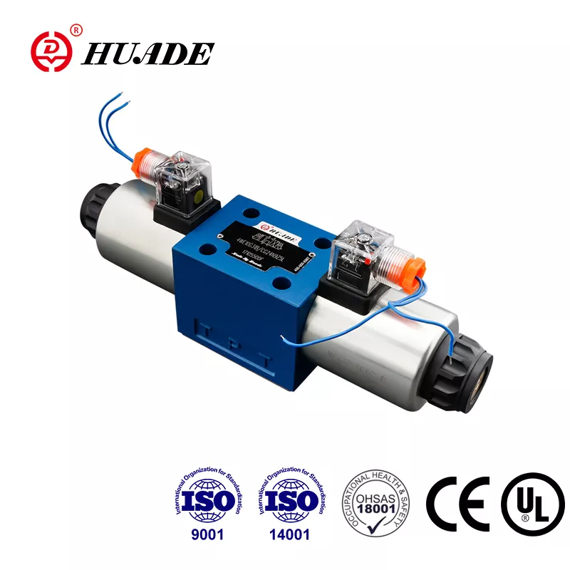
Complex hydraulic circuits often integrate check valves within directional control valve assemblies. These integrated configurations create combined functions such as free flow in one direction with controlled flow in the reverse direction. Pilot-operated check valves frequently pair with directional valves to enable controlled actuator motion in both extend and retract directions while maintaining load position when the directional valve returns to neutral.
Mobile equipment including excavators, bulldozers, and agricultural machinery extensively use hydraulic check valves throughout their hydraulic circuits. These applications demand reliable performance in harsh environments with contamination, vibration, and wide temperature variation.
Troubleshooting Common Hydraulic Check Valve Issues
Contamination-Related Failures
Contamination represents the primary destructive factor in hydraulic check valve failures. Dirt, debris, and metal particles clog valve passages and cause premature wear of critical components. Maintaining fluid cleanliness according to ISO 4406 cleanliness standards prevents contamination damage. Systems operating with cleanliness levels exceeding 19/17/14 typically experience accelerated valve component silting and scoring.
Symptoms of contamination-induced failure include sluggish or inconsistent actuator motion, inability of the check element to fully open or close, and visible fluid leakage around valve body joints. Diagnostic procedures begin with fluid analysis to assess contamination levels and viscosity. If contamination is confirmed, complete system flushing and filter replacement become necessary before installing replacement valves.
Chatter and Vibration Phenomena
Chatter represents a dynamic instability condition manifested as light vibration and clicking noises from the valve. This phenomenon occurs when the hydraulic check valve fails to reach the minimum flow velocity or pressure drop required for full opening. If the valve opens only partially, its flow area remains small and unstable, causing the check element to rapidly oscillate under fluctuating fluid forces.
Engineering strategies to mitigate chatter include adjusting spring characteristics to reduce cracking pressure, allowing full valve opening at lower pressure differential. Another critical approach involves deliberately downsizing the valve relative to line size, particularly for poppet or ball check valves. Selecting valve size based on actual flow requirements rather than simply matching pipe diameter strategically increases pressure drop across the valve. This increased pressure drop forces the valve rapidly into fully open stable operation, eliminating chatter.
The design trade-off between acceptable pressure loss and stable full-open operation is necessary to ensure dynamic system stability. Actual flow velocity must satisfy minimum requirements to keep the valve fully open, preventing dynamic wear and unstable operation.
Hydraulic Shock (Water Hammer)
Hydraulic shock, commonly known as water hammer, describes massive pressure surges or waves generated when moving fluid is suddenly forced to stop or change direction. This phenomenon most commonly occurs when valves at pipeline ends close suddenly and rapidly.
Water hammer damage ranges from noise and vibration in minor cases to pipe rupture or structural collapse in severe scenarios. Certain traditional check valve designs including swing check, tilting disc, and double door configurations inherently slam closed quickly due to their structural characteristics, making them prone to inducing water hammer.
Key mitigation strategies focus on preventing rapid valve closure during high flow conditions. Engineering measures include installing accumulators, expansion tanks, surge tanks, or pressure relief valves to absorb pressure waves. Selecting check valve designs with controlled closing speeds reduces shock severity.
Pressure-Related Degradation
Operating continuously at or beyond design pressure limits stresses seal elements and weakens internal valve structures. Excessive fluid temperature or incorrect viscosity degrades lubrication performance and erodes valve function over time. System designers must ensure operating conditions remain within valve ratings, including transient pressure spikes from actuator deceleration or directional valve shifting.
Symptoms indicating overpressure stress include external leakage from valve body or connections, internal leakage manifested as load drift in holding applications, and physical deformation of valve components visible during disassembly. Pressure testing according to ISO 10771 standards confirms valve integrity and identifies degraded seal performance requiring component replacement.
Installation-Related Faults
Improper installation frequently causes subsequent valve failures. Common installation errors include misalignment creating side loads on the check element, incorrect torque application damaging threads or distorting valve bodies, and skipping critical steps such as verifying flow direction markings.
Professional diagnostic procedures require systematic observation and testing. Visual inspection identifies leakage, loose connections, or physical damage. Fluid sampling and analysis reveals contamination and viscosity problems. Pressure gauges confirm system pressure remains within design ranges. Actuator response monitoring detects inconsistent timing or incomplete motion indicating internal valve degradation.
| Symptom | Description | Potential Root Cause | Mitigation/Diagnostic Action |
|---|---|---|---|
| Chatter/Vibration | Light clicking noise and oscillation, unstable flow | Insufficient pressure drop/velocity; valve not fully opening; improper sizing | Reduce spring cracking pressure; downsize valve to increase pressure drop |
| Severe Slamming Noise | Violent impact noise during closure | Rapid valve closing; sudden change in fluid momentum (water hammer) | Install slow-closing valve design; use accumulators or surge tanks |
| Sticking/Sluggish Response | Inconsistent or incomplete opening/closing | Contamination (dirt/debris); incorrect fluid viscosity; high temperature stress | Perform fluid analysis; clean internal components; verify operating temperature |
| Leakage (Internal/External) | Fluid escaping through seals or valve body | Overpressure stress; soft seal wear; improper installation | Pressure test per ISO 10771; replace seals; verify torque and alignment |
Industry Standards and Quality Compliance
ISO 4401 Interchangeability Standard
ISO 4401 specifies mounting flange and interface dimensions for hydraulic valves, ensuring interchangeability and compatibility among valve bodies from different manufacturers. This standardization drives global supply chain efficiency and supports modular design approaches. The strategic significance for international maintenance, repair, and operations (MRO) processes cannot be overstated, as standardized interfaces simplify component sourcing and reduce inventory requirements.
ISO 10771 Testing Protocols
ISO 10771-1:2015 establishes common test methods applicable to multiple hydraulic fluid power components. Quality control procedures typically require pressure testing hydraulic check valves to 1.5 times their rated pressure, maintaining this proof pressure for a specified duration to verify structural stability and leak-tight performance. These rigorous test protocols validate component integrity before release to service.
CE Marking and SIL Certification
CE certification demonstrates product compliance with European Union machinery safety and pressure equipment directives. This marking represents mandatory conformance for products sold in EU markets. Additionally, Safety Integrity Level (SIL) certification becomes critical for valves applied in safety-critical circuits. SIL ratings quantify the probability of a safety system performing correctly when demanded, with higher SIL levels indicating greater reliability. Systems requiring high functional safety, such as emergency shutdown circuits, specify SIL-rated components to meet overall safety performance targets.
Selection Considerations for Engineering Applications
Successful hydraulic check valve selection requires systematic evaluation of multiple interdependent factors. Flow requirements, including maximum and minimum flow rates, determine valve size and style. Pressure conditions, encompassing normal operating pressure, maximum system pressure, and potential transient spikes, dictate pressure rating requirements and structural design.
Fluid characteristics significantly influence material selection. Fluid type, temperature range, viscosity, and cleanliness level affect seal material compatibility, internal clearance specifications, and component durability. Applications involving contaminated fluids or wide temperature swings require more robust designs with higher tolerance for adverse conditions.
Installation envelope constraints often drive configuration choice between inline, cartridge, or subplate mounting styles. Space limitations in mobile equipment or compact machinery favor cartridge designs that integrate into manifold blocks. Maintenance accessibility requirements may justify subplate configurations despite higher initial installation complexity.
Response time requirements influence the choice between direct-acting and pilot-operated designs. Applications demanding instantaneous response to flow changes typically specify direct-acting valves. Conversely, systems prioritizing precise pressure control and high flow capacity justify the complexity and cost of pilot-operated configurations.
The fundamental distinction between static load holding and dynamic load control must guide valve selection. For static applications where loads remain stationary for extended periods, pilot-operated check valves deliver excellent performance at reasonable cost. Dynamic applications requiring controlled lowering of gravity loads absolutely require counterbalance valves with integrated flow metering capability to prevent dangerous instability.
Life cycle cost analysis should weigh initial component cost against operating efficiency, maintenance requirements, and replacement frequency. Valves engineered for lower pressure drop reduce continuous energy consumption, delivering payback over extended service life despite potentially higher purchase prices. Harsh operating environments justify premium components with superior contamination resistance and extended service intervals.
The global hydraulic valve market continues expanding, driven by industrial automation advancement, energy infrastructure investment, and increasing emphasis on energy efficiency and environmental sustainability. Market projections indicate the hydraulic valve sector will reach $16.82 billion by 2035, growing at a 6.03% compound annual growth rate. This expansion reflects continued hydraulic technology evolution and integration with digital control systems.
Future technology trajectories emphasize smart valves incorporating Industrial Internet of Things (IIoT) connectivity for enhanced monitoring, real-time data feedback, and optimized performance. Predictive maintenance capabilities represent core advantages of these intelligent systems, identifying incipient failures before they cause system downtime. Electrohydraulic actuators (EHO) combine hydraulic power with electrical control precision, offering fail-safe operation for critical applications such as emergency shutdown valves.
Engineering and procurement departments should prioritize products conforming to ISO 4401 and ISO 10771 international quality standards. Long-term strategic planning should consider investment in IIoT-enabled electrohydraulic solutions supporting predictive maintenance and remote diagnostics. These advanced systems optimize performance while reducing operational risk through continuous health monitoring and early fault detection.
Hydraulic check valves remain indispensable components ensuring directional control and system protection in fluid power applications. Their apparent simplicity conceals sophisticated engineering trade-offs among pressure stability, energy efficiency, dynamic response, and sealing integrity. Proper selection demands careful analysis of application requirements, operating conditions, and life cycle cost implications. As hydraulic systems evolve toward greater automation and intelligence, check valve technology continues advancing to meet increasingly demanding performance and reliability expectations.


