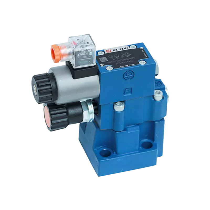
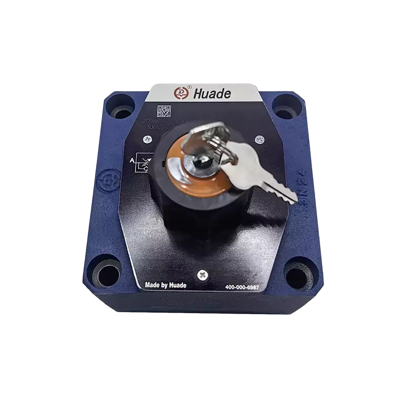
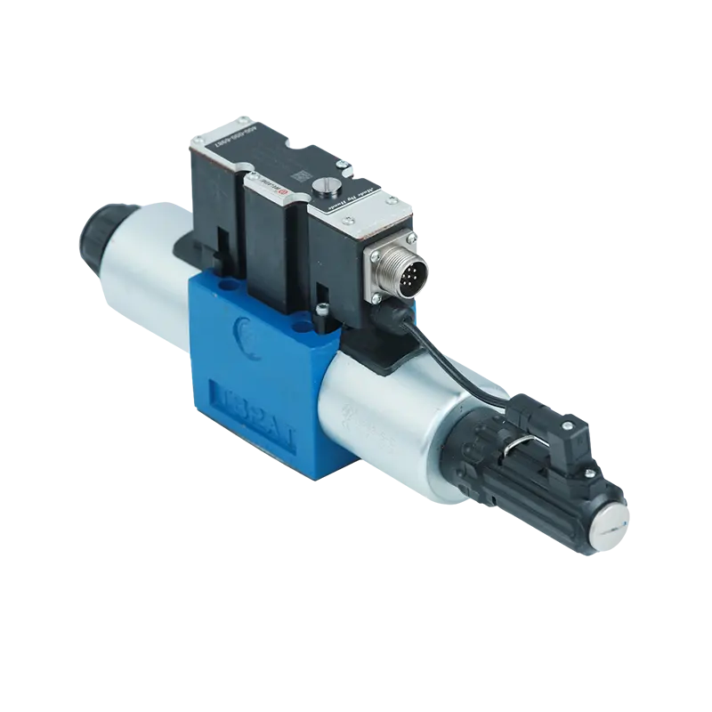
A directional control valve (DCV) is a hydraulic or pneumatic component that manages the flow path of working fluid within a power transmission system. The valve controls whether fluid flows, where it flows, and when the flow starts or stops. By changing these flow directions, a directional valve determines how actuators like hydraulic cylinders or motors move, making it the command center for any fluid power circuit.
[Image of directional control valve cross section diagram]Think of a directional control valve as a railway switch operator. Just as a switch directs trains onto different tracks, a directional valve routes pressurized fluid to different ports and channels. This routing capability allows a single pump or compressor to power multiple actuators in various directions and sequences. The valve sits between the power source (pump) and the working components (cylinders, motors), translating control signals into precise fluid movements.
In fluid power engineering, three fundamental control elements determine system behavior: direction control, pressure control, and flow control. The directional valve handles the first responsibility exclusively, though its switching characteristics directly affect the other two parameters. When a directional valve changes position, momentary pressure spikes can occur, requiring coordination with pressure relief valves. Similarly, the valve's internal flow passages influence the system's overall flow resistance and energy efficiency.
The Working Mechanism: Spool and Poppet Designs
Directional valves achieve flow control through two primary mechanical designs: spool valves and poppet valves. Each design offers distinct advantages based on application requirements.
Spool Valve Operation
Spool valves represent the most common directional control design in hydraulic systems. The core mechanism consists of a precisely machined cylindrical spool that slides axially within an equally precise bore. The spool features raised lands (sealing sections) and recessed grooves (flow channels). As the spool moves, the lands align with or block various ports drilled into the valve body, creating or breaking fluid connections.
The fit between spool and bore requires micrometer-level precision. A typical clearance ranges from 5 to 25 micrometers, depending on valve size and pressure rating. This tight tolerance allows the spool to move freely while minimizing internal leakage. The small clearance creates a thin oil film that provides lubrication during spool movement. However, this same clearance makes spool valves inherently prone to internal leakage, with some fluid continuously bypassing from high-pressure to low-pressure chambers.
This precision fit also creates vulnerability. Contamination particles approaching the clearance dimension can wedge between the spool and bore, causing spool sticking. When the spool cannot move freely, the valve fails to respond to control signals, potentially leaving actuators in unintended positions. This sensitivity explains why spool valve reliability directly correlates with hydraulic fluid cleanliness levels.
Poppet Valve Construction
Poppet valves use a different sealing approach. A cone-shaped or ball-shaped element presses against a matching seat to block flow. When control force lifts the poppet off its seat, fluid passes through the opened passage. The metal-to-metal or elastomer-reinforced sealing contact achieves zero or near-zero leakage, making poppet valves ideal for circuits requiring long-term pressure holding without drift.
The rigid sealing contact limits poppet valve applications compared to spool designs. Poppet valves typically function as two-position devices (open or closed) and cannot easily provide the complex mid-position functions or flow modulation capabilities of multi-land spool valves. The spring force and fluid pressure that must be overcome to open the poppet also result in higher actuation forces and sometimes slower response compared to balanced spool designs.
| Characteristic | Spool Valve | Poppet Valve |
|---|---|---|
| Leakage Performance | Low internal leakage present (5-50 mL/min typical) | Zero or near-zero leakage |
| Position Complexity | Can achieve 2, 3, or more positions with various mid-functions | Typically limited to 2-position operation |
| Switching Speed | Fast response (10-50 ms typical) | Moderate response due to spring and pressure forces |
| Contamination Sensitivity | High sensitivity; requires ISO 4406 18/16/13 or cleaner | Lower sensitivity; more tolerant of particle contamination |
| Pressure Holding | Gradual pressure decay due to internal leakage | Maintains pressure indefinitely |
Classification by Port and Position Configuration
The industry standard method for classifying directional valves uses an "N-way M-position" naming convention. This system precisely describes valve connectivity and functionality.
The first number (N) indicates the number of ports or "ways" the valve provides for external connections. These ports serve specific functions. In hydraulic systems, common port designations include P for pressure supply, A and B for connections to actuator chambers, T for tank return, and sometimes X and Y for pilot control signals. Pneumatic valves follow similar conventions with numbered ports according to ISO 5599 standards.
The second number (M) specifies how many stable positions the valve spool or element can maintain. Each position creates a different internal flow path configuration by connecting certain ports while blocking others. A valve might connect P to A in one position, then connect P to B in another position, directing fluid to opposite sides of a cylinder.
Common Valve Configurations
**2-way 2-position (2/2) valves** function as simple on-off controls. One position blocks flow completely; the other allows flow to pass. These valves appear in applications like machine lockout circuits or basic cylinder control where only forward motion requires power.
**3-way 2-position (3/2) valves** suit single-acting cylinders or actuators with spring return. The valve alternately connects pressure to the actuator (extending it) or connects the actuator to tank (allowing spring-driven retraction). Many pneumatic cylinders use this arrangement since compressed air exhausts to atmosphere rather than returning to a reservoir.
**4-way 3-position (4/3) valves** represent the most versatile configuration for industrial hydraulics. These valves control double-acting cylinders or bidirectional motors. The three positions typically provide extend, retract, and a center condition. The center position design determines critical system behavior when the valve sits in neutral.
Different center position configurations serve distinct purposes. An "O" or closed center blocks all four ports, hydraulically locking the actuator in place but also trapping the pump output with no flow path. This requires a separate pump unloading mechanism. An "H" or open center connects all ports together, allowing the actuator to float freely while the pump circulates fluid to tank at minimal pressure. A "P" or tandem center blocks the work ports (A and B) to hold the actuator position while connecting pump to tank for unloading. Engineers select center configurations based on whether they need position holding, free movement, or pump unloading during neutral conditions.
**5-way valves** typically appear in pneumatic applications, providing pressure supply, two work ports, and two separate exhaust ports. The dual exhausts allow independent control of cylinder end venting, which matters when back pressure affects actuator behavior or when one cylinder chamber exhausts must route separately for noise or contamination reasons.
| Valve Type | Port Functions | Position Capability | Common Applications |
|---|---|---|---|
| 2/2 Valve | P (pressure), A (outlet) | Open/Closed | Safety lockout, simple on-off control, pilot supply isolation |
| 3/2 Valve | P, A, T (tank/exhaust) | Pressurize/Exhaust | Single-acting cylinders, pneumatic clamps, spring-return actuators |
| 4/3 Valve | P, A, B, T | Extend/Hold/Retract | Double-acting cylinders, hydraulic motors, positioning systems |
| 5/2 Valve | P, A, B, EA, EB (exhausts) | Extend/Retract | Pneumatic cylinders with separate exhaust control |
| 5/3 Valve | P, A, B, EA, EB | Extend/Center/Retract | Complex pneumatic sequences requiring mid-position functions |
Actuation Methods: How Valves Receive Control Signals
Directional valves shift between positions using various actuation mechanisms. The choice depends on control distance, automation requirements, available power sources, and response speed needs.
Manual Actuation
Manual operation through levers, pushbuttons, or pedals provides direct mechanical control. These methods suit applications where operators work near the equipment or where simple, reliable control without electrical dependencies matters. Some manually operated valves include detent mechanisms that hold the selected position until the operator changes it again. Others use spring return, automatically centering when the operator releases the control.
Solenoid (Electromagnetic) Actuation
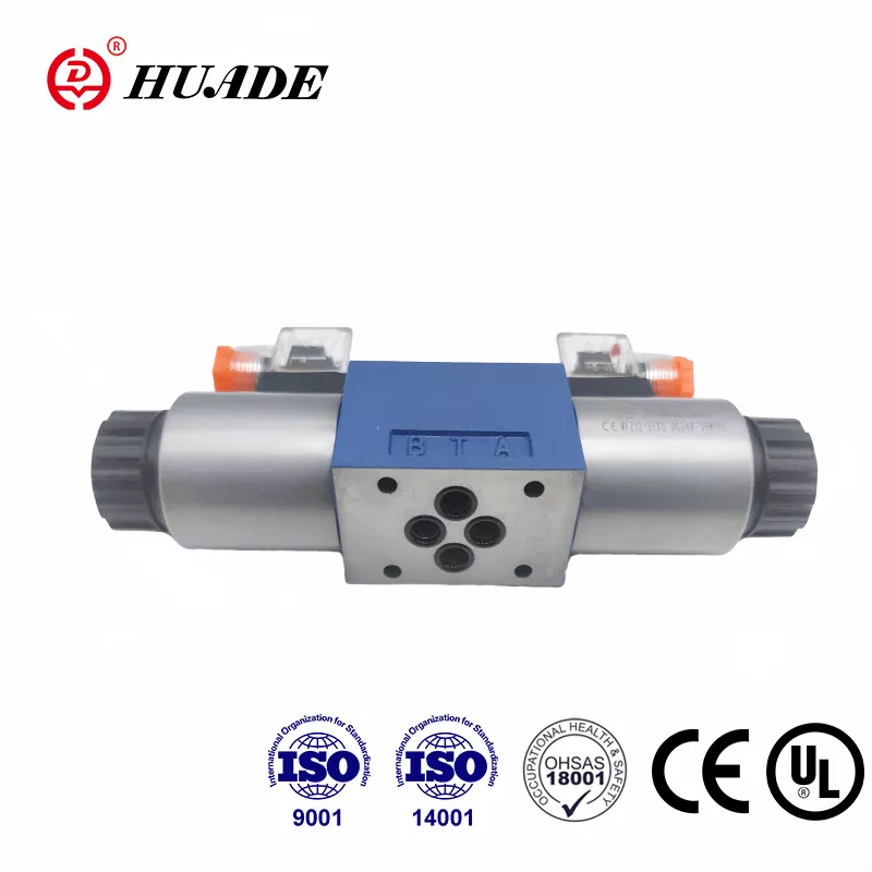
Solenoid actuation dominates modern automated systems. An electromagnetic coil generates magnetic force that pulls a plunger, which then shifts the valve spool. Solenoids enable remote control and integration with programmable logic controllers (PLCs) or other electronic control systems.
Solenoids operate on either alternating current (AC) or direct current (DC) power. DC solenoids provide smoother engagement with less mechanical shock and noise compared to AC solenoids. The magnetic force in DC coils remains constant, while AC solenoids experience force fluctuations at line frequency (50 or 60 Hz) causing vibration and buzzing. For this reason, industrial valve designs often incorporate internal rectifier circuits even when AC power supplies the valve. The rectifier converts AC input to DC, driving the solenoid with smooth direct current while maintaining compatibility with facility AC power systems.
Response time for solenoid valves typically ranges from 15 to 100 milliseconds depending on valve size, spring stiffness, and solenoid power. Faster response requires more powerful solenoids, which increases electrical power consumption and generates more heat. Applications like rapid cycling or precise timing sequences need careful solenoid specification to balance speed against power requirements and coil temperature limits.
Pilot Actuation
Pilot actuation uses fluid pressure itself to shift the valve. Small pilot valves (often solenoid-operated) direct control pressure to chambers at each end of the main valve spool. The pressure differential across the spool generates force that moves it to the commanded position. This arrangement provides a force multiplication effect, allowing a small electrical signal to a pilot valve to control a much larger main valve handling high flow and pressure.
Pilot-operated valves overcome the practical size and power limitations of direct solenoid actuation. Direct acting solenoid valves rarely exceed 100 liters per minute flow capacity because larger spools require proportionally larger electromagnetic forces to shift against spring and fluid forces. Pilot operation handles flow rates exceeding 1000 liters per minute using compact solenoid pilot valves drawing only 10-20 watts of electrical power.
The two-stage design trades response speed for force multiplication. A typical pilot-operated valve responds in 50-150 milliseconds compared to 15-50 milliseconds for similar-sized direct acting valves. The delay comes from the time needed to pressurize and depressurize the pilot chambers as the spool moves. For many industrial applications, this trade-off proves acceptable given the dramatic improvement in flow handling capacity.
Understanding ISO 1219 Valve Symbols
Fluid power schematics use standardized symbols defined by ISO 1219 to represent valve functions without showing physical construction details. This symbolic language allows engineers worldwide to read and design hydraulic and pneumatic circuits regardless of language barriers or specific component manufacturers.
In ISO 1219 notation, each valve position appears as a square box. A three-position valve shows three adjacent boxes. The ports connect to lines extending from the outermost boxes. Inside each box, arrows indicate flow paths active in that position, while blocked ports show T-junctions or solid lines. The actuation methods appear as symbols at the ends of the box assembly - triangles for solenoids, rectangles with diagonal lines for manual levers, or spring symbols for spring return mechanisms.
Reading a valve symbol requires identifying the box representing the current or neutral position, then tracing which ports connect through that box. When the valve shifts to another position, the adjacent box slides over (conceptually), and the flow paths shown in that box become active. This visual method quickly communicates valve logic without requiring detailed understanding of internal spool geometry or seal arrangements.
Industrial Applications Across Sectors
Directional valves enable automated motion control in countless industrial processes. Their applications span from massive construction equipment to precision manufacturing systems.
- Mobile hydraulics relies heavily on directional valves to coordinate multiple functions. An excavator operator controls boom, stick, bucket, and swing functions through a bank of directional valves, each regulating a different hydraulic cylinder or motor.
- Manufacturing automation employs directional valves to sequence operations like clamping, pressing, and part transfer. A robotic welding station might use dozens of directional valves to position workpieces, activate clamps, and control weld tip actuators.
- Process industries use directional valves for mixing operations, gate and diverter control, and emergency shutdown functions. A directional valve might route process fluid between different tanks or redirect flow during abnormal conditions.
- Marine and offshore applications require directional valves that withstand corrosive environments and maintain function during extended periods without maintenance. Ship steering systems and subsea equipment depend on robust directional control valves.
Performance Parameters and Selection Criteria
Selecting an appropriate directional valve requires matching multiple performance specifications to application demands.
Maximum Operating Pressure
The pressure rating indicates the maximum sustained pressure the valve body and seals can handle without failure or excessive leakage. Hydraulic directional valves commonly rate between 210 and 420 bar (3000-6000 psi) for industrial applications, with specialized designs reaching 700 bar or higher for heavy-duty mobile equipment. Pneumatic valves typically operate at much lower pressures, from 6 to 10 bar (87-145 psi), matching standard compressed air systems.
The pressure rating must exceed the maximum system pressure including any pressure spikes that occur during load changes or pump start-up. A safety margin of 25-30% above normal operating pressure provides reasonable protection against unexpected transients.
Flow Capacity and Pressure Drop
Flow capacity (Q) specifies the maximum flow rate the valve can pass while maintaining acceptable pressure drop and temperature rise. Pressure drop (ΔP) represents the pressure loss between inlet and outlet ports at rated flow. This loss converts to heat and wasted energy.
The relationship between flow, pressure drop, and power loss follows the equation:
Where power loss appears in watts when flow uses liters per minute and pressure drop uses bar (with appropriate unit conversion factors). Modern high-efficiency directional valves achieve rated flows of 60-100 liters per minute with pressure drops below 1 bar. This low-pressure-drop design reduces heat generation and pump power requirements, directly improving system energy efficiency and reducing cooling system demands.
For example, a valve passing 80 liters per minute with 2 bar pressure drop wastes approximately 266 watts (80 L/min × 2 bar × 16.67 W/bar/LPM). Reducing pressure drop to 0.5 bar cuts this loss to 67 watts, saving 199 watts continuously during operation. Over thousands of operating hours, this difference translates to significant energy costs and reduced oil degradation from heat.
Response Time and Switching Characteristics
Response time measures the interval between control signal application and complete valve position change. Fast response enables rapid motion reversal and precise timing in automated sequences. However, extremely fast switching can generate destructive pressure spikes (water hammer) when suddenly stopping high-velocity fluid columns.
Advanced directional valves incorporate soft-shift or ramp features that control spool acceleration during position changes. These features intentionally slow the initial spool movement to gradually redirect flow, then complete the shift quickly once fluid velocity has decreased. The result combines reasonable response time with reduced shock loading on system components.
| Parameter | Typical Range | Engineering Significance |
|---|---|---|
| Maximum Pressure |
210-420 bar (hydraulic) 6-10 bar (pneumatic) |
Determines structural integrity and seal reliability under load |
| Rated Flow (Q) | 20-400 L/min (common industrial) | Must meet actuator speed requirements at operating pressure |
| Pressure Drop (ΔP) | 0.5-2 bar at rated flow | Directly affects energy efficiency and heat generation |
| Response Time | 15-150 ms depending on actuation type | Influences cycle time and motion precision |
| Internal Leakage | 5-50 mL/min (spool valves) | Affects positioning accuracy and heat load during holding |
| Operating Temperature |
-20°C to +80°C (standard) -40°C to +120°C (extended) |
Limits fluid viscosity range and seal material selection |
Mounting and Interface Standards
Mechanical mounting interfaces follow ISO 4401 standards (previously known as CETOP or NFPA standards). Common sizes include NG6 (also called D03), NG10 (D05), and NG25 (D08), with the number indicating the mounting surface bolt pattern and port size. Standardized mounting ensures interchangeability between manufacturers and simplifies system design using modular manifold blocks.
Manifold mounting concentrates multiple valves on a single machined aluminum or steel block containing internal flow passages. This approach eliminates external piping between valve and actuator ports, reducing potential leak points, improving packaging density, and allowing optimized internal flow channels with minimal turbulence and pressure loss.
Advanced Control: Proportional and Servo Valves
While on-off directional valves provide adequate control for many applications, some systems require continuous adjustment of flow and direction rather than discrete switching.
Proportional Valve Technology
Proportional directional valves use variable force solenoids or torque motors to position the spool continuously rather than just at end positions. The spool displacement becomes proportional to the input current signal, allowing infinitely variable flow control within the valve's range. This capability enables smooth acceleration and deceleration, precise speed control, and gentle load handling impossible with switching valves.
High-performance proportional valves incorporate position feedback sensors, typically linear variable differential transformers (LVDTs) that monitor actual spool position. A closed-loop controller compares commanded position to actual position, adjusting solenoid current to eliminate position error. This feedback mechanism achieves precise spool positioning despite friction variations, pressure forces, and temperature effects.
Modern proportional valves feature hysteresis below 1% of full stroke. Hysteresis represents the position difference when approaching a target from increasing versus decreasing directions. Low hysteresis ensures consistent response regardless of previous spool movement direction, critical for precise motion control and preventing position oscillation.
Some proportional valves employ pressure feedback principles, sensing actuator load pressure and modulating flow to compensate for load changes. This pressure compensation maintains more consistent actuator speed under varying loads without requiring external flow compensators. The technique improves system stiffness and control precision in applications like material testing machines or forming presses where loads change during the work cycle.
Servo Valves for Critical Applications
Servo valves represent the highest performance level in directional control technology. These devices achieve frequency responses exceeding 100 Hz with position resolution below 0.1% of stroke. Aerospace flight control surfaces, naval ship steering systems, and material testing machines that must precisely control force or position at high frequencies all rely on servo valve capabilities.
Servo valve designs typically use two-stage construction with a first-stage nozzle-flapper or jet-pipe mechanism controlling second-stage spool position. The first stage provides high precision with minimal power, while the second stage delivers the flow capacity needed for actuators. However, the narrow clearances and small orifices in first-stage designs make servo valves extremely sensitive to contamination. Fluid cleanliness requirements often specify ISO 4406 codes of 16/14/11 or cleaner - far more stringent than the 18/16/13 acceptable for standard directional valves.
Safety in Hazardous Environments
Industrial valves operating in explosive atmospheres require special certification to prevent ignition sources. ATEX (Atmosphères Explosibles) certification for European markets and equivalent IECEx standards for international applications specify design requirements for electrical components like solenoids in potentially explosive environments.
Explosion-protected directional valves employ flameproof enclosures that contain any internal spark or hot surface, preventing ignition of external gases. The solenoid housing uses robust construction with specially machined mating surfaces that prevent flame propagation even if internal ignition occurs. Some designs use intrinsically safe circuitry that limits electrical energy to levels incapable of ignition under fault conditions.
These safety-certified valves enable proportional control technology in chemical processing plants, oil refineries, pharmaceutical manufacturing, and mining operations where combustible materials present constant explosion risks. The integration of advanced control capability with rigorous safety standards demonstrates how modern valve technology serves demanding and dangerous applications.
Common Failure Modes and Maintenance Practices
Despite careful design, directional valves experience wear and failure modes that affect system performance and safety. Understanding these failure mechanisms guides effective maintenance strategies.
Spool Sticking and Contamination
Spool sticking represents the most frequent directional valve failure in hydraulic systems. The condition occurs when friction between spool and bore exceeds the available actuation force, preventing spool movement. Root causes include contamination particles lodged in clearance spaces, varnish deposits from oxidized hydraulic oil, moisture corrosion, and mechanical scoring from previous particle intrusion.
Contamination control provides the primary defense against spool sticking. Hydraulic fluid cleanliness must meet or exceed valve manufacturer specifications, typically requiring filtration to ISO 4406 cleanliness codes between 18/16/13 for standard valves and 16/14/11 for proportional valves. These codes specify maximum particle counts at 4, 6, and 14 micrometer sizes per 100 milliliters of fluid. Each three-step increase in code number represents a doubling of particle concentration.
Operating temperature affects contamination buildup rates. Hydraulic systems running above 80°C accelerate oil oxidation, producing varnish and sludge that coat valve spools and restrict movement. Cooling system capacity must maintain oil temperature within the 40-65°C range for optimal valve life and reliability. Temperature excursions during high-demand periods or inadequate cooler sizing gradually degrade system cleanliness even with proper filtration.
Internal Leakage Progression
Internal leakage past spool lands increases gradually as surfaces wear during normal operation. Acceptable leakage rates for new spool valves range from 5-20 milliliters per minute depending on valve size and design. As wear progresses, leakage can reach 50-100 milliliters per minute before requiring valve replacement.
Excessive internal leakage manifests as slower actuator movement, inability to maintain pressure during holding periods, and increased oil heating from internal flow circulation. Leakage testing involves measuring flow from blocked ports or comparing actuator speeds under load against baseline measurements. Progressive monitoring detects wear trends before critical failures occur.
Solenoid and Electrical Failures
Solenoid coils fail from electrical overstress, thermal overload, moisture ingress, or mechanical damage. Continuous-duty solenoids rated for 100% duty cycle can operate indefinitely at rated voltage and maximum ambient temperature. Intermittent-duty solenoids require off periods for cooling and will fail from overheating if cycled too rapidly or held energized continuously.
Voltage variations outside the specified range (+/-10% typical) accelerate coil failure. Low voltage reduces magnetic force, potentially causing incomplete spool shifting or slow response. Excessive voltage increases current draw and heat generation, degrading coil insulation until short circuits occur. Rectifier failures in AC-powered valves cause unusual coil behavior as unrectified AC reaches the DC solenoid, creating oscillating magnetic forces and excessive heating.
Diagnostic procedures for suspected solenoid failures include resistance measurement (comparing to nameplate values), voltage verification at the solenoid connection during attempted operation, and manual override testing to isolate electrical from mechanical problems. Many industrial proportional and pilot-operated valves include manual override mechanisms that allow mechanical spool shifting even when electrical systems fail, providing critical emergency functionality.
| Failure Mode | Typical Causes | Symptoms | Diagnostic Method |
|---|---|---|---|
| Spool Sticking | Contamination, varnish buildup, corrosion, mechanical scoring | No response to control signals, erratic motion, slow or incomplete shifting | Manual override test, oil cleanliness analysis, visual inspection after disassembly |
| Excessive Internal Leakage | Spool/bore wear, surface scratches, seal degradation | Slow actuator speed, pressure decay during holding, increased oil temperature | Flow measurement from blocked ports, actuator speed comparison tests |
| Solenoid Coil Failure | Voltage extremes, thermal overload, moisture, insulation breakdown | No magnetic pull, weak actuation, burning smell, tripped protection | Resistance check, voltage verification, current measurement, manual override test |
| Spring Failure | Fatigue from cycling, corrosion, overstress from pressure spikes | Incomplete return to neutral, failure to shift positions, stuck valves | Manual operation feel test, disassembly inspection |
| External Seal Leakage | O-ring aging, improper installation, chemical attack, pressure/temperature cycling | Visible fluid seepage, mounting surface wetness, pressure loss | Visual inspection, pressure hold test after isolating valve section |
Preventive Maintenance Guidelines
Effective directional valve maintenance focuses on protecting the precision spool-bore interface and electrical components from degradation.
Fluid quality management forms the foundation. Establish baseline fluid cleanliness through laboratory analysis of new oil and periodically verify cleanliness levels during operation. Target ISO 4406 codes appropriate for installed valve types. Replace filter elements at recommended intervals regardless of differential pressure indicators, as depth-type filters can reach capacity for fine particles while differential pressure remains low.
Temperature monitoring helps detect abnormal conditions before damage occurs. Excessive temperature indicates inadequate cooling capacity, flow restrictions creating pressure drop, or internal leakage generating heat. Install temperature sensors at critical locations including valve manifold blocks, particularly on proportional valves generating more heat from internal leakage and electrical power dissipation.
Develop systematic inspection and testing procedures. Record baseline performance data including actuator cycle times, maximum pressures achieved, and solenoid current draw during commissioning. Periodic comparison against baseline reveals gradual degradation trends. Response time measurements using pressure transducers and data acquisition systems detect increasing friction or contamination before complete failure.
System designers should specify valves with manual override capabilities for critical functions. Manual overrides provide emergency operation during electrical failures and enable diagnostic isolation between mechanical and electrical fault sources. The override mechanism also allows verification of actuator and load operation independent of valve electrical systems during troubleshooting.
The Evolution of Directional Control Technology
Directional valve technology continues advancing along several parallel paths, each addressing specific industry demands.
Integration represents a major trend. Modern valves increasingly incorporate onboard electronics including CAN bus or Industrial Ethernet communication, built-in diagnostics monitoring coil current and temperature, and self-calibration routines that compensate for wear and temperature effects. These smart valves shift from passive components to active system participants that report health status and predict maintenance needs.
Energy efficiency drives continuous improvement in flow path design and materials. Computer-aided flow simulation optimizes internal passages to minimize turbulence and pressure loss. Some manufacturers now specify pressure drop below 0.5 bar at rated flow for standard directional valves, half the typical values from previous decades. Lower pressure drops reduce heat generation and pump power consumption, supporting corporate sustainability goals and operating cost reduction.
Miniaturization pushes control capability into smaller packages. Valve cartridge designs that mount in custom manifolds achieve high flow capacity from remarkably compact envelopes. These configurations serve mobile equipment where space and weight critically limit system design.
The future likely brings deeper integration between fluid power valves and digital control systems. Electrification in mobile equipment creates opportunities for fully electric actuator control replacing traditional pilot hydraulics. Condition monitoring through valve-integrated sensors enables predictive maintenance strategies that schedule service based on actual component health rather than fixed intervals. These developments will extend directional valve capability while improving reliability and sustainability across fluid power applications.


