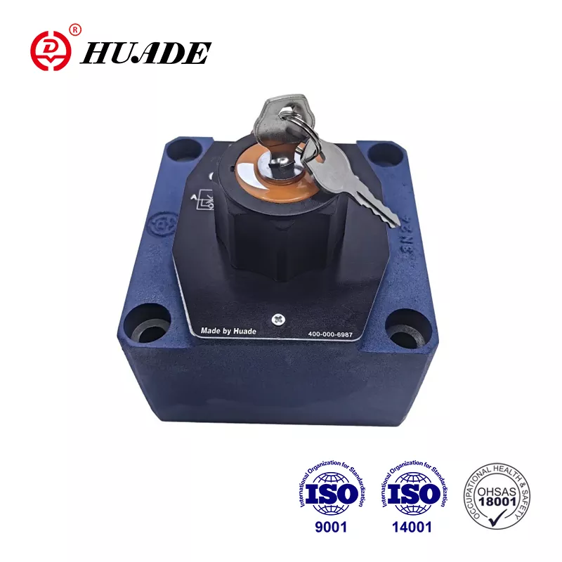
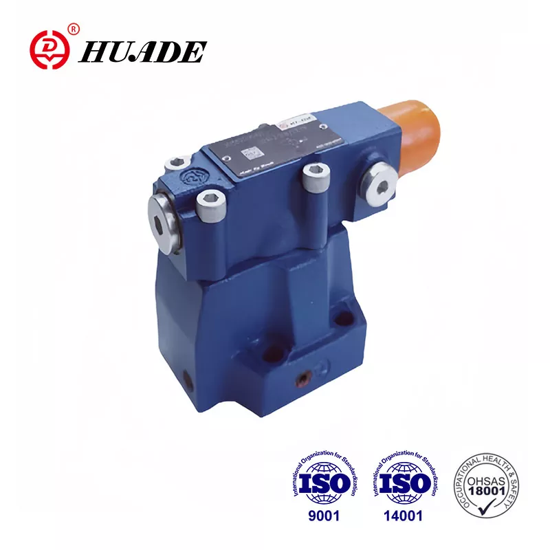
When engineers and technicians search for "what are the three types of valves," they're often surprised to find that there's no single universal answer. The truth is more nuanced than a simple three-category list. The classification of valves depends entirely on the operational context, whether you're working with hydraulic power systems, industrial process piping, or mechanical actuator integration.
This complexity isn't a bug in engineering terminology—it's a feature. Different industrial disciplines have developed their own classification frameworks because they prioritize different valve characteristics. A hydraulic system designer focuses on control functions, while a process plant engineer cares about service duty, and a maintenance technician needs to understand mechanical motion types for actuator selection and spatial planning.
In this comprehensive guide, we'll explore the three most authoritative classification frameworks that define valve types across different engineering contexts. Each framework represents a legitimate answer to the "three types" question, backed by industry standards and real-world application requirements.
Framework One: Functional Classification in Fluid Power Systems
In hydraulic and pneumatic systems, valves serve as the logical executors of power transmission circuits. The three fundamental valve types in this framework are based on control function: directional control valves, pressure control valves, and flow control valves. This classification dominates automation engineering and is explicitly recognized in ISO 1219 (fluid power symbols) and NFPA T3.10.19 standards.
Directional Control Valves
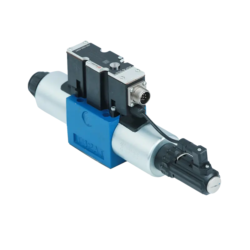
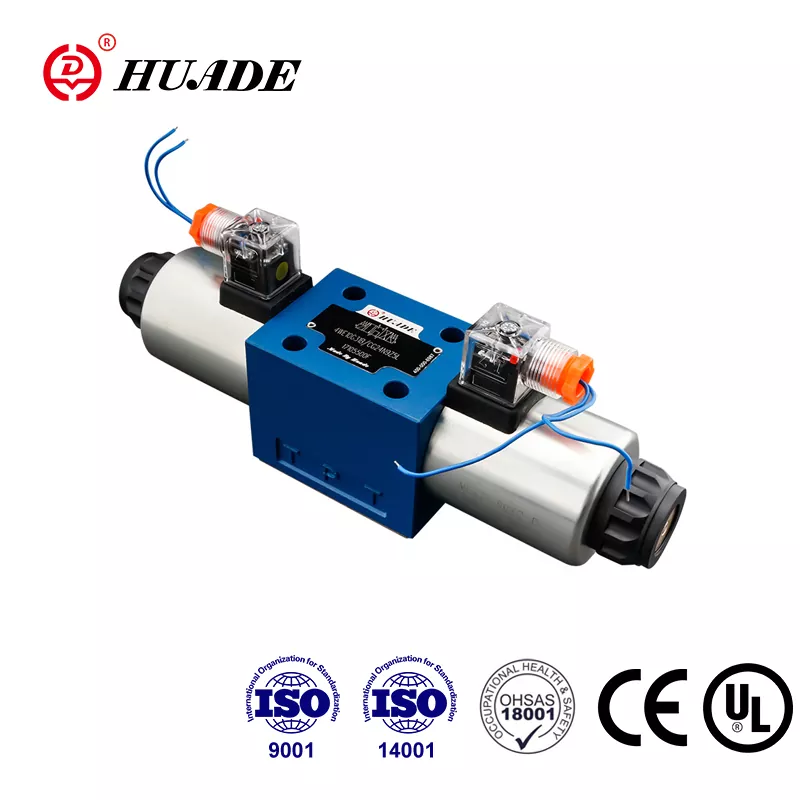
Directional control valves (DCVs) establish the logical foundation of any fluid power system. Their primary function is to route, divert, or block fluid flow paths within a circuit, thereby determining the motion direction of actuators such as hydraulic cylinders (extend, retract, or hold) or hydraulic motors (clockwise, counterclockwise, or stop).
The internal architecture of DCVs falls into two dominant design philosophies: spool valves and poppet valves. Spool valves consist of a precisely machined cylindrical element (the spool) with lands and grooves that slide within a matching bore. As the spool moves axially, it covers or uncovers ports in the valve body, redirecting fluid paths. This design excels at implementing complex switching logic—a single valve body can achieve 4-way 3-position or 5-way 2-position configurations. However, spool valves have an inherent physical characteristic called clearance sealing. To allow smooth sliding motion, there must be a radial clearance of several micrometers between the spool and bore. This creates unavoidable internal leakage (spool bypass) under pressure, making spool valves unsuitable for long-term load holding without auxiliary check valves.
Poppet valves, in contrast, use a movable closing element (cone, ball, or disc) that presses against a seat perpendicular to flow. This creates a contact seal or face seal. When closed, system pressure actually assists in pressing the element more tightly against the seat, achieving positive, near-zero leakage sealing. This makes poppet valves ideal for load-holding, safety cutoff, and high-pressure isolation applications. The stroke is typically short, resulting in extremely fast response times, and the opening action provides a self-cleaning effect that gives poppet designs superior contamination tolerance compared to spools.
The specification of DCVs follows a standard notation system based on "ways" (number of fluid ports) and "positions" (number of stable spool states). A 4-way 3-position valve (4/3), for example, has four ports—pressure (P), tank (T), and two work ports (A, B)—and three stable positions. The center condition of 3-position valves is critical for system behavior. An O-type closed center blocks all ports, locking actuators in position but causing pump pressure buildup. An H-type float center connects A, B, and T while blocking P, allowing the actuator to float freely. A Y-type tandem center connects P and T while blocking A and B, unloading the pump to tank and reducing heat generation while maintaining actuator lock.
Pressure Control Valves
In hydraulic physics, pressure equals force per unit area ($$P = F/A$$). Therefore, controlling system pressure is essentially controlling actuator output force. Pressure control valves limit maximum system pressure or regulate localized circuit pressure to maintain safe operating conditions and achieve force control objectives.
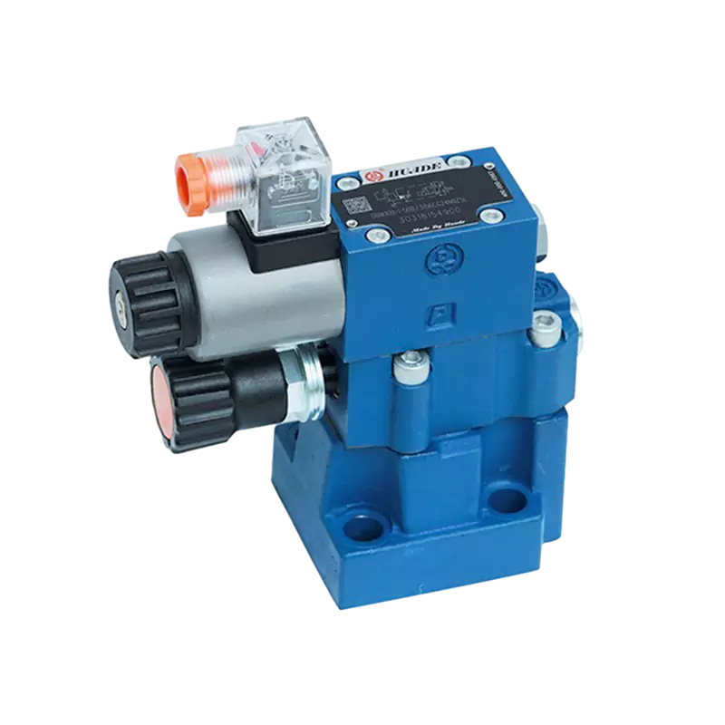
The relief valve serves as the safety cornerstone—a normally-closed valve connected in parallel with the system. When system pressure exceeds the spring-set force threshold, the valve opens and diverts excess fluid back to the tank, thereby limiting maximum system pressure. This prevents catastrophic failure of hoses, seals, and actuators under overload conditions. Direct-operated relief valves respond quickly but exhibit significant pressure override (the difference between cracking pressure and full flow pressure). Pilot-operated relief valves use a small pilot valve to control the main spool opening, providing a flatter pressure-flow characteristic curve that maintains more stable system pressure across wide flow ranges. Pilot-operated designs also facilitate remote pressure adjustment and system unloading functions.
Pressure reducing valves operate on a fundamentally different principle despite visual similarity. These are normally-open valves installed in series within a circuit. They throttle flow to reduce outlet pressure and use outlet pressure feedback to maintain constant reduced pressure regardless of inlet pressure fluctuations. This is essential when a single hydraulic source must serve multiple circuits with different pressure requirements—for example, a main system requiring 20 MPa (2900 psi) for cylinder force while an auxiliary clamping circuit needs only 5 MPa (725 psi).
Sequence valves control the order of operations by remaining closed until inlet pressure reaches a set point, then automatically opening to allow flow to downstream circuits. Unlike relief valves that dump fluid to tank, sequence valves direct outlet flow to working circuits and therefore typically require an external drain connection to handle control chamber leakage without contaminating the work port signal.
Counterbalance valves are critical for hoisting and vertical motion systems. Installed in the return line of a cylinder, they are set to a pressure slightly above what the load creates through gravity. By generating backpressure, they prevent load free-fall under gravitational force, ensuring smooth controlled descent. Modern counterbalance valves integrate a check valve allowing free reverse flow for lifting operations.
Flow Control Valves
Flow control valves regulate fluid volume per unit time through the valve, thereby controlling actuator speed (cylinder extension/retraction velocity or motor rotational speed). The fundamental flow equation through an orifice is $$Q = C_d A \\sqrt{2\\Delta P/\\rho}$$, where Q is flow rate, A is orifice area, and ΔP is pressure differential across the orifice.
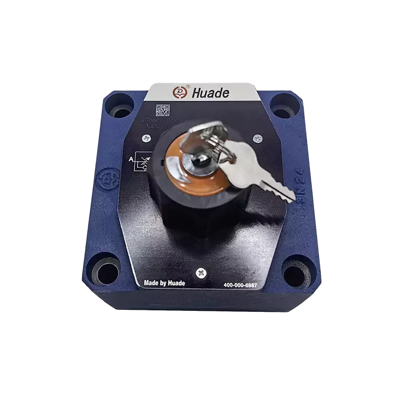
The simplest flow control is a needle valve, classified as non-compensated. From the equation above, flow Q depends not only on opening area A but also on the square root of pressure differential ΔP. If load varies, ΔP varies, causing speed instability. To solve this fundamental problem, pressure-compensated flow control valves incorporate an internal constant-differential pressure reducing valve (the compensator) in series with the throttling orifice. This compensator automatically adjusts its own opening based on load pressure to maintain constant ΔP across the main orifice. With ΔP held constant, flow Q becomes a function only of opening area A, achieving load-independent constant speed control.
The circuit position of flow control valves defines the speed control method. Meter-in control places the valve controlling flow entering the actuator. This suits applications with constant, resistive loads but cannot create backpressure—when facing overrunning loads like gravity-driven motion, the actuator will run away. Meter-out control places the valve controlling flow exiting the actuator. By building backpressure on the return side, this creates more rigid hydraulic support that effectively prevents overrunning load runaway and provides superior motion smoothness. However, the backpressure can cause pressure intensification in the inlet chamber, requiring careful pressure rating verification during design.
| Valve Type | Primary Function | Control Parameter | Typical Applications | Key Standards |
|---|---|---|---|---|
| Directional Control | Route fluid paths | Flow direction | Cylinder sequencing, motor reversing, logic circuits | ISO 5599, NFPA T3.6.1 |
| Pressure Control | Limit or regulate pressure | System/circuit pressure | System protection, force control, load sequencing | ISO 4411, SAE J1115 |
| Flow Control | Regulate flow rate | Actuator speed | Speed control, synchronization, feed rate management | ISO 6263, NFPA T3.9.13 |
Framework Two: Service Duty Classification in Process Piping
When we shift context from fluid power circuits to industrial process plants—encompassing oil and gas, chemical processing, water treatment, and power generation—the three types of valves are classified by their service duty in the piping system. This framework recognizes isolation valves, regulation valves, and non-return valves as the fundamental trinity. This classification dominates P&ID (Piping and Instrumentation Diagram) development and is reflected in piping standards like ASME B31.3 and API 600.
Isolation Valves
Isolation valves (also called block valves or shutoff valves) are designed to allow either full flow or complete blockage. They operate in fully open or fully closed positions and should never be used for throttling service. Prolonged operation in partially open positions causes high-velocity fluid to erode sealing surfaces through a phenomenon called wire drawing, destroying sealing performance and leading to catastrophic leakage.
Gate valves represent the classic linear shutoff design. A wedge-shaped disc moves perpendicular to flow direction to cut off flow. When fully open, the flow path forms a straight-through conduit with minimal pressure drop, making gate valves ideal for services where low resistance is critical. Gate valves come in two stem configurations with different operational characteristics. Rising stem gate valves (OS&Y—Outside Screw and Yoke) have external threads that cause the stem to rise when the handwheel turns. This provides visual position indication—extended stem means open—and keeps threads out of contact with process media, preventing corrosion. These are standard in fire protection systems and critical process lines where position visibility is safety-critical. Non-rising stem gate valves (NRS) have the stem rotating but not translating vertically, with the internal nut threads built into the wedge. This design minimizes vertical space requirements, making them suitable for buried pipelines or confined spaces, but lacks intuitive position indication and exposes threads to media corrosion.
Gate valves require multi-turn operation, meaning slow opening and closing. While this prevents water hammer, it makes them unsuitable for emergency shutoff. The sealing surfaces are also susceptible to galling (cold welding of metal surfaces under pressure and friction).
Ball valves represent the modern standard for rotary shutoff. A sphere with a through-bore serves as the closure element. Rotating 90 degrees achieves full open or full closed operation with speed and efficiency. Full-port ball valves have bore diameters matching the pipe, resulting in negligible flow resistance. The sealing mechanism differs fundamentally between floating ball and trunnion-mounted designs. In floating ball valves, the ball is supported only by the seats and "floats" within the body. Media pressure pushes the ball against the downstream seat, creating tight sealing. This design works for low to medium pressure and small diameters, but in high-pressure large-bore applications, operating torque becomes enormous and seats deform under stress. Trunnion-mounted ball valves mechanically fix the ball between upper and lower trunnions, preventing ball movement. Media pressure pushes spring-loaded seats toward the ball to achieve sealing. This design dramatically reduces operating torque and enables double block and bleed (DBB) functionality, making it the API 6D choice for pipeline transmission and high-pressure applications.
Regulation Valves
Regulation valves (also called control valves or throttling valves) are designed to modulate flow resistance and thereby control flow rate, pressure, or temperature. Unlike isolation valves, they must withstand high velocities, turbulence, and cavitation or flashing that occur during partial opening. They never simply open and close—they live in the throttling zone.
Globe valves set the benchmark for precision control. A plug-shaped disc moves along the flow centerline. The internal flow path forms an S-shape, forcing fluid through sharp directional changes. This tortuous path dissipates massive amounts of fluid energy, enabling fine flow modulation. By changing disc contour (linear, equal percentage, quick opening), engineers can define the valve's inherent flow characteristic. Equal percentage characteristics are most common in process control because they compensate for nonlinear system pressure drop changes, maintaining relatively constant control loop gain across the full stroke range. Globe valves offer excellent throttling precision and tight shutoff (disc and seat mate in parallel contact), but high flow resistance creates substantial pressure loss.
Butterfly valves use a disc rotating within the flow stream to control flow. Traditional concentric butterfly valves serve simple low-pressure water systems, but eccentric butterfly valves have entered the high-performance control arena. Double-offset designs have the stem axis offset from both the disc center and pipe centerline. This cam effect causes the disc to rapidly lift away from the seat upon opening, reducing friction and wear. Triple-offset designs add a third angular offset between the seat cone axis and pipe centerline. This achieves true "frictionless" operation, allowing metal-to-metal hard sealing that reaches bubble-tight zero leakage and withstands extreme temperature and pressure. Triple-offset metal-seated butterfly valves dominate severe service steam and hydrocarbon applications.
The physics of valve sizing demands calculation-based selection. The flow coefficient ($$C_v$$) defines the gallons per minute of 60°F water flowing through the valve at 1 psi pressure drop. It serves as the universal metric of valve capacity. The sizing formula $$C_v = Q\\sqrt{SG/\\Delta P}$$ relates flow rate Q, specific gravity SG, and pressure drop ΔP.
Critical to severe liquid service is understanding flashing and cavitation. As fluid accelerates through the valve's vena contracta (minimum area), velocity peaks and pressure reaches its lowest point. Downstream, pressure partially recovers. Flashing occurs when post-vena contracta pressure cannot recover above the liquid's vapor pressure—the liquid permanently vaporizes into two-phase flow, and high-velocity vapor-liquid mixture causes severe erosive damage. Cavitation occurs when vena contracta pressure drops below vapor pressure (forming bubbles), but downstream pressure recovers above vapor pressure. The bubbles implode, generating extreme localized micro-jets and shockwaves that cause catastrophic noise, vibration, and material pitting. The pressure recovery factor ($$F_L$$) characterizes a valve's cavitation resistance. Globe valves typically have high $$F_L$$ values (low recovery), providing superior cavitation resistance compared to ball and butterfly valves (low $$F_L$$, high recovery).
Non-Return Valves
Check valves (non-return valves) are self-actuating devices that open with forward flow and close with reverse flow. They primarily protect pumps from reverse rotation damage and prevent system drainage. Unlike other valve types, they operate without external control signals—fluid momentum and gravity provide the actuation force.
Swing check valves have a disc that rotates around a hinge pin. They offer low flow resistance but are prone to disc chatter in low-velocity or pulsating flow conditions. In applications with rapid flow reversal, swing checks can generate destructive water hammer as the disc slams shut. Lift check valves have a disc that moves vertically, similar in construction to globe valves. They provide tight sealing and withstand high pressure, but exhibit high flow resistance and susceptibility to blockage by debris. Tilting disc check valves represent the premium solution for large pump stations (flood control, water supply). The disc pivot axis sits near the seating surface, creating a balanced airfoil structure. Short stroke enables extremely fast closure with cushioning action, dramatically reducing water hammer pressure spikes.
| Valve Type | Operating Mode | Position States | Throttling Capability | Primary Standards |
|---|---|---|---|---|
| Isolation/Block | On-off only | Fully open or fully closed | Not recommended | API 600, API 6D, ASME B16.34 |
| Regulation/Control | Modulating | Any position in stroke | Primary function | IEC 60534, ANSI/ISA-75 |
| Non-Return | Automatic | Self-actuated by flow | N/A (binary check) | API 594, BS 1868 |
Framework Three: Mechanical Motion Classification for Actuator Integration
The third major classification framework categorizes valves by the physical motion trajectory of their closure element. This perspective is essential for actuator selection (pneumatic, electric, hydraulic), spatial layout planning, and maintenance strategy development. The three types are linear motion valves, rotary motion valves, and self-actuated valves.
Linear Motion Valves
Linear motion valves have closure elements that move in a straight line, either perpendicular or parallel to flow direction. Representative examples include gate valves, globe valves, diaphragm valves, and pinch valves. Linear motion typically converts rotational torque into massive linear thrust through threaded stems, providing excellent sealing force (high unit seating stress). The throttling response tends to be more linear, suitable for high-precision control applications. However, stroke length is typically long, resulting in tall valve heights (significant headroom requirements).
Diaphragm valves and pinch valves deserve special attention within linear valve designs due to their unique "media isolation" characteristic. These valves shut off flow by compressing a flexible diaphragm or elastomeric sleeve, completely isolating the operating mechanism from process media. This provides critical advantages in sanitary applications (pharmaceutical, food and beverage) where contamination prevention is paramount, and in slurry applications (mining, wastewater) where abrasive particles would rapidly destroy metal trim components. The diaphragm or sleeve material selection (PTFE, EPDM, natural rubber) becomes the primary compatibility consideration rather than body metallurgy.
Rotary Motion Valves
Rotary motion valves have closure elements that rotate around an axis, typically 90 degrees to achieve full stroke. Representative examples include ball valves, butterfly valves, and plug valves. These designs offer compact structure, light weight, and fast operation. They excel in space-constrained installations and applications requiring rapid actuation. Fire-safe certification testing per API 607 or API 6FA is common for rotary valves in hydrocarbon service, verifying that metal-to-metal backup sealing engages if soft seats burn away during a fire event.
The torque profile of rotary valves is non-constant across stroke. Peak torque occurs at break-to-open (overcoming static friction and pressure differential) and at end-of-close (compressing seats to final seating). Mid-stroke torque is primarily dynamic fluid torque. Actuator sizing must be based on maximum torque with appropriate safety factors, typically 1.25 to 1.50 for normal service and up to 2.00 for emergency shutdown applications. Pneumatic actuators for rotary valves typically use rack-and-pinion or scotch-yoke mechanisms. Scotch-yoke designs produce a U-shaped torque output curve that naturally matches the high-torque-at-endpoints characteristic of ball and butterfly valves, resulting in higher efficiency and allowing smaller actuator sizing.
Self-Actuated Valves
Self-actuated valves require no external power source—electric, pneumatic, or hydraulic. They operate purely from energy within the process media itself. Check valves use fluid kinetic energy, relief and safety valves use static pressure force, and self-operated pressure regulators use pressure balance feedback. The absence of external power makes these valves intrinsically fail-safe for certain critical applications.
However, self-actuated valves exhibit hysteresis and deadband characteristics due to the physical balance between fluid force and mechanical spring force combined with friction. Hysteresis means the opening pressure and reseating pressure differ—the valve "remembers" its previous state. Deadband is the input range over which no output change occurs. Excessive deadband causes control instability, while appropriate hysteresis (such as the blowdown in relief valves—the difference between set pressure and reseat pressure) is necessary to prevent valve chatter (rapid cycling that damages seats and creates dangerous pressure oscillations). Standards like ASME Section VIII Division 1 (boiler and pressure vessel code) mandate specific performance requirements for self-actuated safety and relief devices.
| Motion Type | Stroke Characteristic | Typical Actuators | Space Requirements | Response Speed |
|---|---|---|---|---|
| Linear Motion | Long stroke, high thrust | Piston cylinder, electric motor + leadscrew | High vertical (headroom) | Slow to moderate |
| Rotary Motion | Quarter-turn (90°) | Rack-pinion, scotch-yoke, electric quarter-turn | Low vertical, moderate radial | Fast |
| Self-Actuated | Variable (media-driven) | None (integral spring/weight) | Minimal (no actuator) | Depends on design |
Choosing the Right Classification Framework for Your Application
Understanding which of these three frameworks to apply depends on your specific engineering context and decision-making priorities. If you're designing an automated manufacturing cell with hydraulic cylinders and need to program motion sequences, the fluid power functional classification (directional, pressure, flow) provides the logical structure you need. Your circuit diagrams will use ISO 1219 symbols that directly correspond to these functional categories, and your troubleshooting approach will focus on which control function has failed.
If you're laying out a chemical process plant or refinery and developing P&IDs, the service duty classification (isolation, regulation, non-return) aligns with how process engineers think about material flow control. Your valve schedule documents will categorize valves by service duty, and your material specifications (API 6D for pipeline ball valves, IEC 60534 for control valves, API 594 for check valves) naturally follow this framework. The distinction matters for procurement—an isolation-duty ball valve may have a different trim material, seat leakage class, and actuator sizing than a throttling-duty ball valve of identical size.
If you're a mechanical maintenance technician planning valve replacement in a congested equipment room, or you're selecting actuation packages, the mechanical motion classification (linear, rotary, self-actuated) drives your practical decisions. You need to know whether you have vertical clearance for a rising stem, whether your existing actuator mounting pattern fits rotary quarter-turn valves, and whether you can access the valve during operation. This classification also affects your spare parts inventory strategy—linear motion valve stems and packing have different wear patterns and replacement procedures compared to rotary valve bearings and seats.
The reality is that experienced engineers fluidly move between these frameworks depending on the question being answered. A control valve in a refinery might simultaneously be described as a flow control valve (fluid power function), a regulation valve (process service duty), and a linear motion valve (mechanical implementation). Each description is correct within its context, and each provides different decision-making information. The key is recognizing that valve classification is not a rigid taxonomy but rather a flexible toolset of perspectives.
Modern valve standards often bridge multiple frameworks. For example, IEC 60534 covers control valves and addresses both functional requirements (flow characteristics, rangeability) and mechanical considerations (actuator attachment, stem design). API 6D covers pipeline valves and specifies service duty performance (isolation and throttling classes) while also detailing mechanical features (rising stem vs. non-rising stem, trunnion mounting requirements). This cross-framework integration reflects how real engineering projects require holistic understanding rather than isolated categorical knowledge.
Conclusion: Context Determines Classification
When someone asks "what are the three types of valves," the technically correct answer begins with a question: three types according to which classification system? The fluid power engineer's answer—directional control, pressure control, and flow control—is perfectly valid within hydraulic and pneumatic automation contexts. The process engineer's answer—isolation, regulation, and non-return—accurately describes industrial piping service duties. The mechanical engineer's answer—linear motion, rotary motion, and self-actuated—correctly categorizes physical implementation and actuator interfaces.
This multiplicity of valid answers is not a failure of standardization but rather a reflection of valve engineering's depth and breadth. Valves operate at the intersection of fluid mechanics, materials science, mechanical design, and control theory. Different technical disciplines naturally develop classification systems that align with their problem-solving approaches and decision-making priorities.
For engineers working across disciplines—such as those designing integrated process control systems or managing plant-wide asset reliability programs—understanding all three frameworks provides strategic advantage. It enables effective communication with specialists from different backgrounds, supports better-informed equipment selection decisions, and facilitates more comprehensive failure analysis. When a valve fails, asking whether it failed in its directional control function, its isolation service duty, or its mechanical actuation reveals different aspects of the root cause and guides different corrective actions.
As valve technology advances with digital positioners, wireless monitoring, and predictive maintenance algorithms, these fundamental classification frameworks remain relevant. A smart valve with embedded diagnostics still performs a functional role (pressure control), serves a process duty (throttling), and operates through a mechanical motion mode (rotary). The digital intelligence layer enhances performance and reliability but doesn't replace the need to understand these foundational categorizations. Whether you're specifying valves for a new facility, troubleshooting a failing system, or optimizing an existing plant, clarity about which type of classification matters in your specific context is the first step toward engineering excellence.


