Hydraulic control valves serve as the decision-making centers of fluid power systems. Every hydraulic circuit depends on these components to regulate three fundamental parameters: the direction of fluid flow, the pressure level within the system, and the rate at which fluid moves through actuators. Understanding hydraulic control valve types is essential for anyone involved in designing, maintaining, or troubleshooting hydraulic systems across industries from manufacturing to aerospace.
The classification of hydraulic control valve types follows a functional framework that has remained consistent across decades of hydraulic engineering practice. This framework divides all hydraulic valves into three primary categories based on what they control. Directional control valves determine where the fluid goes. Pressure control valves manage the force available in the system. Flow control valves regulate how fast actuators move. Within each category exists a range of specialized designs, each engineered to address specific operational requirements.
Understanding Hydraulic Control Valve Classification
The three-pillar classification system for hydraulic control valve types emerged from a practical engineering need: to organize components by their primary function in the hydraulic circuit. This classification is not arbitrary. It reflects the fundamental physics of hydraulic systems, where fluid power can be controlled through directional routing, pressure regulation, or flow restriction.
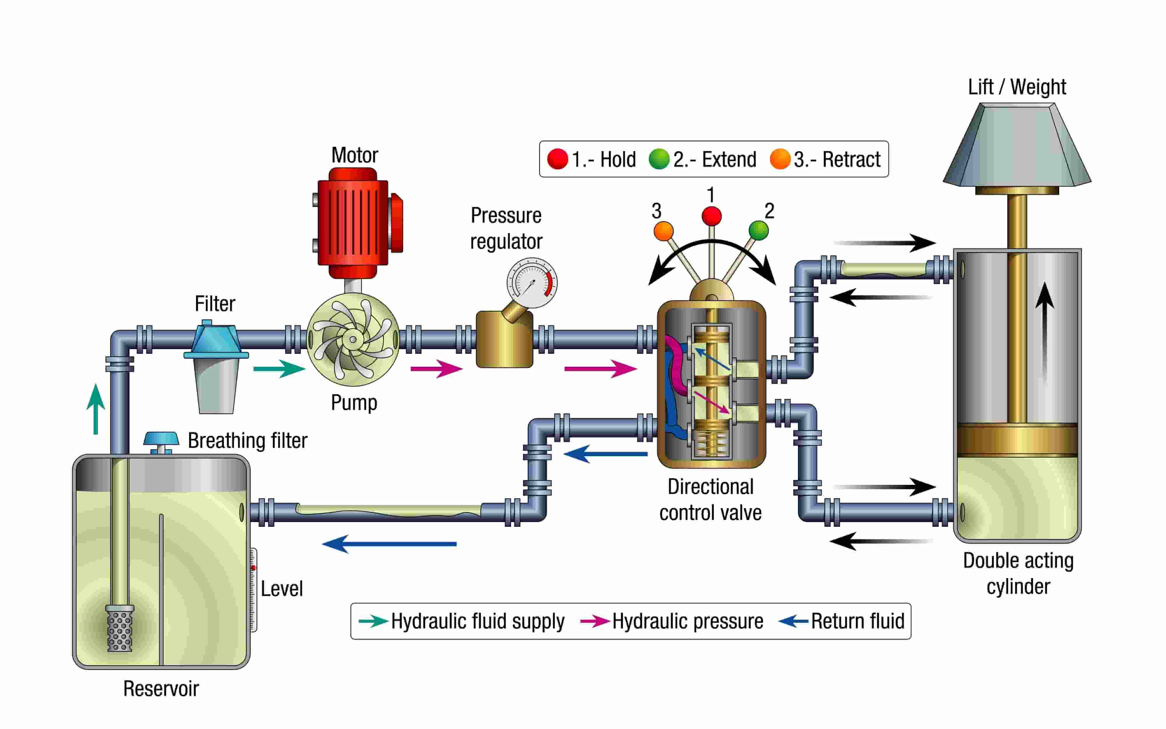
Directional Control Valves (DCVs) manage the path of hydraulic fluid through the system. When an operator activates a lever to extend a cylinder or reverse a motor, a directional control valve redirects the flow from the pump to the appropriate actuator port. These valves do not regulate pressure or flow rate directly; they simply open and close specific fluid pathways. A double-acting cylinder requires a four-way directional valve with connections for pump pressure (P), tank return (T), and two actuator ports (A and B).
Pressure Control Valves (PCVs) maintain safe operating conditions by regulating the force available in the system. Hydraulic pressure represents stored energy, and excessive pressure can rupture hoses, damage seals, or destroy pump components. Pressure control valves respond to changes in system pressure by opening relief paths to the tank or by restricting flow to maintain specific pressure levels in different circuit branches. A relief valve set at 3000 PSI will crack open when system pressure approaches this limit, protecting downstream components from overpressure damage.
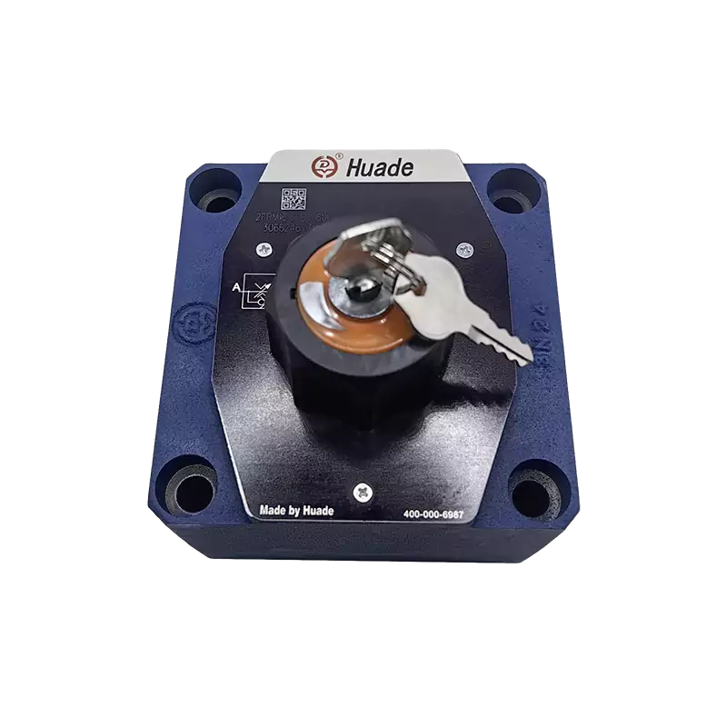
Flow Control Valves (FCVs) determine actuator speed by regulating the volume of fluid passing through the circuit per unit time. The speed of a hydraulic cylinder or motor depends directly on how much fluid enters it. A flow control valve restricts this volume using an orifice or throttle. When load conditions change during operation, compensated flow control valves adjust automatically to maintain consistent actuator speed regardless of pressure variations.
This functional separation means that a single hydraulic circuit typically requires multiple valve types working together. A mobile excavator boom circuit might use a directional control valve to select extend or retract, a counterbalance valve to prevent load drop, and a flow control valve to smooth the motion. Understanding which hydraulic control valve types address which control objectives is the foundation of effective system design.
Directional Control Valves: Managing Flow Paths
Directional control valves are identified using a standardized notation that describes their configuration. The notation follows a "ways and positions" format. A four-way, three-position valve is written as 4/3 (four ports, three switching positions). The number of ways refers to the external connections: typically pressure inlet (P), tank return (T or R), and one or more working ports (A, B, C). The number of positions describes how many stable switching states the valve can maintain.
The most common configuration in industrial hydraulics is the four-way, three-position valve (4/3). This design provides a neutral center position where the valve can be programmed to connect ports in different ways depending on the application. A closed-center valve blocks all ports in neutral, allowing the pump to be unloaded. An open-center valve returns pump flow directly to tank at low pressure, reducing energy consumption when no work is being performed. A tandem-center configuration unloads the pump while allowing actuators to float freely.
The internal mechanism of directional control valves falls into two fundamental designs: spool valves and poppet valves. The engineering trade-off between these designs shapes their application range.
Spool valves use a cylindrical element with precisely machined lands that slides within a bore to cover and uncover ports. The clearance between the spool and bore must be minimal (typically 5-25 microns) to reduce internal leakage while still allowing smooth movement. This design excels in applications requiring multiple flow paths and smooth transitions between positions. Pilot-operated, four-way, three-position spool valves are standard in mobile equipment because they can handle complex center port configurations. However, the necessary clearance means spool valves have inherent internal leakage, which can cause actuator drift when holding loads for extended periods.
Poppet valves use a disc or cone element that seats against a valve face, typically aided by spring force and inlet pressure. When closed, the poppet creates metal-to-metal or elastomer-to-metal contact, achieving zero leakage. This design provides the fastest response times and highest flow capacity for a given envelope size. Modern compact poppet-type directional control valves following DIN standards can achieve cycle rates exceeding 100 operations per minute with no measurable leakage in the closed state. The limitation of poppet valves appears in applications requiring complex flow routing or intermediate positioning.
| Characteristic | Spool Valve | Poppet Valve |
|---|---|---|
| Internal Leakage | Small but present (due to clearance) | Zero when closed |
| Flow Path Complexity | Excellent (multiple port configurations) | Limited (simpler routing) |
| Response Speed | Moderate | Very fast (2-5 ms typical) |
| Load Holding Capability | Limited (actuator drift possible) | Excellent (no drift) |
| Contamination Sensitivity | Moderate to high | Moderate |
| Typical Applications | Mobile equipment, industrial automation | Load holding, clamping, safety systems |
The choice between spool and poppet designs reflects the priority hierarchy in the application. For high-pressure clamping fixtures or crane load holding where zero leakage is mandatory, poppet valves are specified despite their limitations in flow routing flexibility. For continuous modulation applications like excavator controls, spool valves provide the necessary smooth transitions even though their internal leakage requires periodic adjustment or replacement of worn components.
Actuation methods for directional control valves include manual levers, mechanical cams, pneumatic pilots, hydraulic pilots, solenoid operators, and proportional electronic controls. The selection depends on whether the application requires on-off switching or continuous positioning, how much force is available for actuation, and whether remote or automated control is needed.
Pressure Control Valves: System Safety and Regulation
Pressure control valves maintain system integrity by preventing destructive overpressure conditions and by establishing specific pressure levels in different circuit branches. The most fundamental pressure control component is the relief valve, which acts as a safety backstop for the entire hydraulic system.
Relief valves open when system pressure exceeds a preset limit, diverting flow to the tank and preventing pressure from rising further. All closed-loop hydraulic circuits require relief valve protection. Without this protection, a blocked actuator or closed directional valve would cause pressure to rise until something fails—typically a burst hose, blown seal, or damaged pump. Relief valves are characterized by their cracking pressure (where they begin to open) and their full-flow pressure (where they pass maximum rated flow).
The internal design of relief valves divides into two categories with significantly different performance characteristics.
Direct-acting relief valves use system pressure acting directly on a poppet or spool element against an adjustable spring. When pressure force exceeds spring force, the valve opens. The simplicity of this design provides extremely fast response, typically 5-10 milliseconds, with some designs responding in 2 milliseconds. This rapid response effectively limits pressure spikes during sudden load changes or pump stalls. However, direct-acting valves exhibit a large pressure override—the difference between cracking pressure and full-flow pressure can be 300-500 PSI or more. At high flow rates, this pressure override can generate significant heat and noise, sometimes producing the characteristic "screaming" sound of an overloaded direct-acting relief valve.
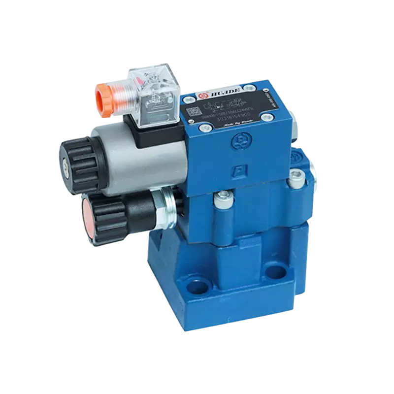
Pilot-operated relief valves use a two-stage design where a small pilot valve controls a larger main valve element. System pressure acts on the pilot stage, which uses the pressure differential to precisely position the main spool or poppet. This design achieves much tighter pressure control with override typically limited to 50-100 PSI even at full rated flow. Pilot-operated valves run quieter and generate less heat during relief operation. The compromise is response time: building pilot pressure and moving the main valve element requires approximately 100 milliseconds, significantly slower than direct-acting designs.
| Performance Parameter | Direct-Acting Relief Valve | Pilot-Operated Relief Valve |
|---|---|---|
| Response Time | 5-10 ms (very fast) | ~100 ms (slower) |
| Pressure Override (cracking to full flow) | 300-500 PSI (large) | 50-100 PSI (minimal) |
| Pressure Stability | Moderate | Excellent |
| Flow Capacity | Limited to moderate | High |
| Noise Level During Relief | Can be high (screaming) | Quiet |
| Cost & Complexity | Lower, simpler | Higher, more complex |
| Best Application | Transient spike protection | Main system pressure control |
The slow response of pilot-operated relief valves creates a specific vulnerability: during sudden pressure spikes, the valve may not open fast enough to prevent damage. Systems with rapid load changes or frequent directional valve shifting often use a hybrid protection strategy. A small, fast-acting direct-acting relief valve is set slightly above the main pilot-operated valve. During normal operation, the pilot-operated valve maintains stable pressure. During transient spikes, the direct-acting valve opens within 5-10 milliseconds to clip the peak, then closes as the pilot-operated valve takes over. This combination maximizes both spike protection and steady-state pressure control.
Beyond basic relief functions, specialized pressure control valves address specific circuit requirements:
- Pressure reducing valves limit pressure in a branch circuit to a level below the main system pressure. A grinding operation might need 1000 PSI while the main system runs at 3000 PSI. A reducing valve maintains the lower pressure in the grinding circuit, protecting sensitive components and preventing excessive force on the workpiece.
- Sequence valves remain closed until inlet pressure reaches a preset level, then open to allow flow to a secondary function. In a drill press, a sequence valve ensures the clamp cylinder completes its stroke (causing system pressure to rise) before allowing the drill cylinder to advance. This prevents drilling into an unsecured workpiece.
- Counterbalance valves prevent runaway loads in vertical or overrunning applications. These valves combine a pilot-operated relief valve with an integral check valve. Installed in the actuator return line, the counterbalance valve creates back pressure that supports the load. Pilot pressure from the extending side modulates the valve to allow controlled descent. Without counterbalance valves, gravity loads would free-fall, and motor-driven loads would overrun. The design includes adjustable pilot ratios, with load-adaptive counterbalance valves automatically adjusting their pilot ratio based on load conditions to optimize stability and energy efficiency.
- Unloading valves divert pump flow to tank at low pressure when system pressure reaches a setpoint signaled by an external pilot. These valves appear in accumulator circuits and high-low pump circuits. When an accumulator is fully charged, an unloading valve responds to the accumulator pilot signal and dumps pump flow to tank, reducing energy consumption and heat generation while maintaining pressure in the accumulator.
Flow Control Valves: Speed and Rate Management
Flow control valves regulate actuator speed by restricting the volume of fluid passing through the circuit. Since actuator velocity is directly proportional to flow rate (velocity = flow rate / piston area), controlling flow rate provides precise speed control for cylinders and motors.
The simplest flow control device is the throttle valve or needle valve—essentially an adjustable orifice. Turning the adjustment creates a variable restriction in the flow path. Flow rate through an orifice follows the relationship Q = CA√(ΔP), where Q is flow rate, C is a flow coefficient, A is orifice area, and ΔP is pressure drop across the orifice. This reveals the fundamental limitation of simple throttle valves: flow rate depends on both the orifice setting and the pressure differential across it.
When load pressure changes—such as when a cylinder moves from horizontal to vertical orientation, changing the gravitational load—the pressure differential across the throttle changes. This causes flow rate to vary even though the orifice setting remains constant. The result is inconsistent actuator speed that varies with load conditions. For applications where approximate speed control suffices and cost is critical, simple throttle valves remain useful. However, precision applications require compensation.
Pressure-compensated flow control valves (PCFCVs) solve the load-dependency problem by maintaining a constant pressure drop across the metering orifice regardless of load variations. The valve contains two elements: an adjustable throttling orifice that sets desired flow, and a compensator spool that responds to pressure feedback.
The compensator spool acts as a mechanical pressure regulator. It senses outlet pressure and positions itself to maintain a fixed pressure differential across the metering orifice. When load pressure increases, the compensator spool moves to increase restriction before the metering orifice, keeping ΔP constant. When load pressure decreases, the spool opens further. Because ΔP remains constant and the metering orifice area is fixed, flow rate Q stays nearly constant regardless of downstream pressure changes.
Pressure-compensated flow control valves can be configured for meter-in control (regulating flow entering the actuator) or meter-out control (regulating flow leaving the actuator). Meter-out configuration is particularly important for controlling loads that can overrun, such as vertically descending cylinders. By restricting the return flow, meter-out control prevents the load from free-falling and provides stable, controlled descent.
The dynamic performance of pressure-compensated flow control valves depends on how quickly the compensator spool responds to pressure changes. In mobile equipment and construction machinery where load conditions change constantly, the compensator spool undergoes continuous adjustment. This frequent movement causes mechanical wear on the spool, spring, and sealing surfaces. For highly dynamic applications, specifying flow control valves with hardened spools, wear-resistant coatings, and high-quality springs is essential to prevent premature degradation and maintain speed control accuracy over the valve's service life.
Temperature compensation adds another layer of sophistication. Hydraulic oil viscosity changes significantly with temperature—typically becoming 5-10 times thinner as temperature rises from 20°C to 80°C. Since flow through an orifice depends partly on viscosity, flow rates can vary with oil temperature even in pressure-compensated designs. Temperature-compensated flow control valves incorporate a temperature-sensitive element that adjusts the effective orifice area to counteract viscosity changes, maintaining truly constant flow across the operating temperature range.
Advanced Electrohydraulic Control Systems
Traditional hydraulic valves operate in discrete states: fully open, fully closed, or switched between specific positions. Advanced applications requiring precise positioning, smooth velocity transitions, or variable force control demand continuous valve modulation. This requirement led to the development of electrohydraulic valves that accept electrical command signals and provide proportional or servo-quality response.
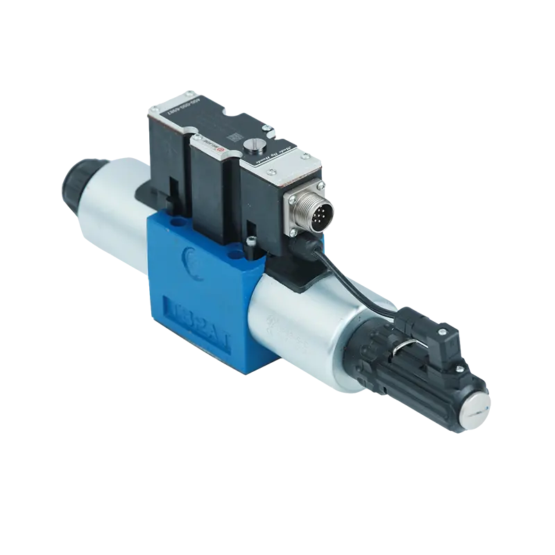
Proportional valves represent the first level of continuous electrohydraulic control. These valves use pulse-width modulated (PWM) electrical signals to drive proportional solenoids that generate variable force on the valve spool. By modulating solenoid current, the valve spool can be positioned anywhere within its stroke, not just at discrete detents. This allows smooth ramping of actuator speed, precise intermediate positioning, and programmable acceleration profiles.
The control resolution of proportional valves depends on the quality of the proportional solenoid and the electrical driver. Modern proportional valves achieve position resolution better than 0.1% of full stroke, with response times typically in the 50-200 millisecond range. Hysteresis (difference in position between increasing and decreasing command signals) is generally held below 3% of full stroke in quality proportional valves.
Proportional valves offer a favorable cost-to-performance ratio for many industrial and mobile applications. They tolerate fluid contamination better than servo valves, typically operating reliably at ISO cleanliness codes around 17/15/12. This makes them suitable for construction equipment, agricultural machinery, and industrial presses where absolute precision is not required but smooth, controlled motion is valuable. A hydraulic excavator uses proportional valves to provide the operator with fine control over boom, stick, and bucket movements, allowing delicate operations while maintaining robust performance in contaminated environments.
Servo valves represent the highest level of hydraulic control precision. Unlike proportional valves that simply position a spool based on electrical input, servo valves incorporate internal feedback loops that continuously compare actual spool position to commanded position and make corrections. This closed-loop internal control, combined with sophisticated designs using torque motors and flapper-nozzle pilot stages, achieves response times under 10 milliseconds and positioning accuracies exceeding 0.01% of full stroke.
The performance of servo valves comes with stringent requirements. The internal clearances in servo valves are extremely tight—typically 1-3 microns—allowing minimal internal leakage but creating extreme sensitivity to contamination. A single wear particle larger than the spool clearance can cause the valve to stick or fail. Industry experience consistently identifies fluid contamination as responsible for 70-90% of hydraulic component failures, with servo valves being the most vulnerable components.
| Characteristic | Proportional Valve | Servo Valve |
|---|---|---|
| Control Accuracy | Medium to high (~0.1% resolution) | Extremely high (~0.01% resolution) |
| Response Time | 50-200 ms | <10 ms |
| Internal Feedback | No (open-loop spool control) | Yes (closed-loop spool positioning) |
| Contamination Tolerance | Good (ISO 17/15/12) | Very poor (requires ISO 16/13/10 or cleaner) |
| Initial Cost | Moderate | High |
| Maintenance Requirements | Standard filtration | Aerospace-grade filtration, strict protocols |
| Typical Applications | Mobile equipment, industrial machines, presses | Aerospace flight controls, precision robots, flight simulators |
Specifying servo valves represents a total system commitment. Achieving and maintaining ISO 16/13/10 cleanliness requires high-efficiency filters (typically β25 ≥ 200), frequent oil sampling and analysis, sealed reservoirs with air breathers incorporating filtration, strict assembly cleanliness procedures, and comprehensive operator training. The filtration system alone can cost more than the servo valve. Organizations considering servo valve technology must understand that the valve purchase price is only the beginning; the real cost lies in maintaining the ultra-clean fluid conditions that servo valve performance depends on.
Selection Criteria and Industry Standards
Selecting appropriate hydraulic control valve types requires systematic evaluation of operating conditions, performance requirements, and lifecycle considerations. The selection process typically follows a structured framework.
Operating parameters define the boundary conditions within which the valve must function:
- Maximum system pressure: Valves must be rated above peak system pressure with appropriate safety margin (typically 1.3x to 1.5x working pressure)
- Flow rate requirements: Valve flow capacity must exceed maximum circuit demand to avoid excessive pressure drop and heat generation
- Fluid compatibility: Seal materials and valve body materials must resist degradation from the hydraulic fluid (petroleum oil, water-glycol, synthetic esters, etc.)
- Operating temperature range: Seals and lubricants must function across the anticipated temperature extremes
- Cycle rate: Valves subject to rapid cycling need designs that resist fatigue and wear
Functional requirements determine which valve category and specific features are needed:
- For directional control: Number of ports, number of positions, center condition, zero leakage requirement, pilot operation
- For pressure control: Relief setting, override characteristics, remote venting capability, load-holding capacity
- For flow control: Pressure compensation, temperature compensation, meter-in vs meter-out, adjustability range
Actuation method depends on available control signals and automation requirements:
- Manual operation for infrequent adjustments or emergency controls
- Hydraulic pilot for remote control using hydraulic signal lines
- Pneumatic pilot in facilities with existing compressed air systems
- Solenoid operation for electrical on-off control and PLC integration
- Proportional/servo control for continuous modulation and closed-loop positioning
Standardization through ISO/CETOP provides significant practical benefits. The ISO 4401 standard defines mounting interface dimensions for hydraulic directional control valves. Valves from different manufacturers that conform to the same ISO mounting pattern (such as ISO 03, commonly called CETOP 03 or NG6/D03) can be interchanged on the same subplate or manifold without modification. This standardization:
- Simplifies spare parts inventory (multiple brands can substitute)
- Reduces engineering time (standard interfaces eliminate custom mounting designs)
- Facilitates upgrades (newer technology valves can replace older designs directly)
- Correlates roughly with flow capacity (ISO 03 valves typically handle up to 120 L/min, ISO 05 up to 350 L/min)
The ISO mounting size becomes a preliminary filter in valve selection. After determining required flow rate, engineers select an appropriate ISO size, then evaluate specific valve models within that size category.
Fluid Contamination and System Integrity
The performance and longevity of all hydraulic control valve types depend critically on fluid cleanliness. Contamination represents the single greatest threat to hydraulic system reliability, with industry data indicating that 70-90% of component failures trace back to contaminated fluid.
Contamination mechanisms damage valves through several pathways:
- Particle interference occurs when solid contaminants enter the clearance between moving valve elements and the bore. In spool valves, particles can score the precisely machined surfaces or jam between the spool and housing, causing sticking. In poppet valves, particles can prevent proper seating, leading to leakage. Servo valves with 1-3 micron clearances are particularly vulnerable—a single 5-micron particle can cause complete failure.
- Abrasive wear happens as hard particles pass through valve orifices and across sealing surfaces at high velocity. This gradually erodes material, increasing clearances and reducing sealing effectiveness. Over time, flow control accuracy degrades, pressure control becomes imprecise, and internal leakage increases.
- Seal degradation accelerates when contaminants include water, acids, or incompatible chemicals. These substances attack elastomers and cause swelling, hardening, or decomposition. Even small amounts of water (as little as 0.1% by volume) can reduce seal life by 50% or more.
- Thermal effects compound the problem: contaminated systems run hotter due to increased friction and reduced efficiency. Higher temperatures accelerate oil oxidation, which produces more contaminants, creating a self-reinforcing failure cycle.
ISO 4406 cleanliness codes provide the industry-standard method for quantifying fluid contamination. The code uses three numbers representing particle counts at three size thresholds: 4 microns, 6 microns, and 14 microns. Each number corresponds to a range of particles per milliliter of fluid. For example, ISO code 18/16/13 indicates:
- Code 18 at ≥4μm: 1,300 to 2,500 particles/mL
- Code 16 at ≥6μm: 320 to 640 particles/mL
- Code 13 at ≥14μm: 40 to 80 particles/mL
Lower ISO code numbers indicate cleaner fluid. Each decrease by one code number represents approximately a 50% reduction in particle count.
| Component Type | Pressure Range | Target ISO 4406 Code (4/6/14μm) | Sensitivity Level |
|---|---|---|---|
| Gear/Vane Motors | Low to medium (<2000 PSI) | 20/18/15 | Most tolerant |
| Standard Directional Valves | Low to medium (<2000 PSI) | 19/17/14 | Moderately tolerant |
| Proportional Valves | All ranges | 17/15/12 | Moderately sensitive |
| High-Pressure Proportional Valves | High (>3000 PSI) | 16/14/11 | Highly sensitive |
| Servo Valves | All ranges | 16/13/10 or cleaner | Extremely sensitive |
| High-Pressure Axial Piston Pumps | High (>3000 PSI) | 16/14/11 | Highly sensitive |
System filtration strategy must target the cleanliness level required by the most sensitive component. A circuit containing a servo valve must maintain ISO 16/13/10 throughout, even if other components could tolerate dirtier conditions. This typically requires:
- High-efficiency filters with beta ratios β25 ≥ 200 (removing 99.5% of particles larger than 25 microns)
- Multiple filtration points (suction, pressure, and return line filters)
- Offline kidney-loop filtration for continuous fluid conditioning
- Sealed reservoir with filtered air breathers
- Regular oil analysis with particle counting
- Strict procedures during maintenance and component installation
The filtration system should process the entire system volume multiple times per hour. A common specification is to filter the total fluid volume at least 3-5 times per hour during operation, with additional kidney-loop filtration continuously polishing the oil.
Beyond particulate contamination, fluid degradation from oxidation, thermal breakdown, and water ingress requires periodic fluid analysis and replacement. Modern hydraulic fluids include additive packages that extend service life, but these additives deplete over time. Fluid sampling at regular intervals (typically every 500-1000 operating hours for critical systems) provides early warning of degradation before component damage occurs.
The economic argument for aggressive contamination control is compelling. While high-quality filters and strict maintenance protocols increase operating costs, these costs are negligible compared to the expense of premature component failure, unscheduled downtime, and lost production. Industry studies consistently demonstrate that every dollar spent on proper filtration saves $5-10 in maintenance and replacement costs over the system lifecycle.
Modern hydraulic systems increasingly incorporate condition monitoring sensors that provide real-time contamination data. Inline particle counters measure cleanliness continuously, alerting operators when contamination exceeds target levels. Pressure sensors at filter locations indicate when elements need replacement. Temperature and flow sensors detect efficiency losses that may indicate internal wear. This transition from time-based maintenance to condition-based maintenance optimizes system uptime while reducing unnecessary component replacement.
Understanding hydraulic control valve types—their classification, operating principles, performance characteristics, and maintenance requirements—forms the foundation for designing reliable, efficient hydraulic systems. The functional categorization into directional, pressure, and flow control provides a logical framework for selecting appropriate components. Within each category, specific valve designs address particular engineering challenges, from achieving zero leakage to maintaining constant speed under varying loads.
The selection process must balance performance requirements against contamination sensitivity and maintenance capabilities. High-precision servo valves deliver exceptional control but demand aerospace-grade cleanliness. Robust proportional valves provide good performance with more forgiving maintenance requirements. Simple throttle valves offer basic functionality at minimal cost but cannot maintain consistent speed under load.
System integrity ultimately depends on maintaining fluid cleanliness appropriate for the most sensitive components in the circuit. Contamination control is not optional—it is the fundamental requirement that determines whether components achieve their design life or fail prematurely. As hydraulic systems continue to evolve with digital integration and smart sensors, the underlying principles of contamination control, proper valve selection, and systematic maintenance will remain central to achieving reliable, efficient operation.
```

