Jiangsu Huafilter Hydraulic Industry Co., Ltd.
News

What does a pressure valve do?

Pressure Valve Guide

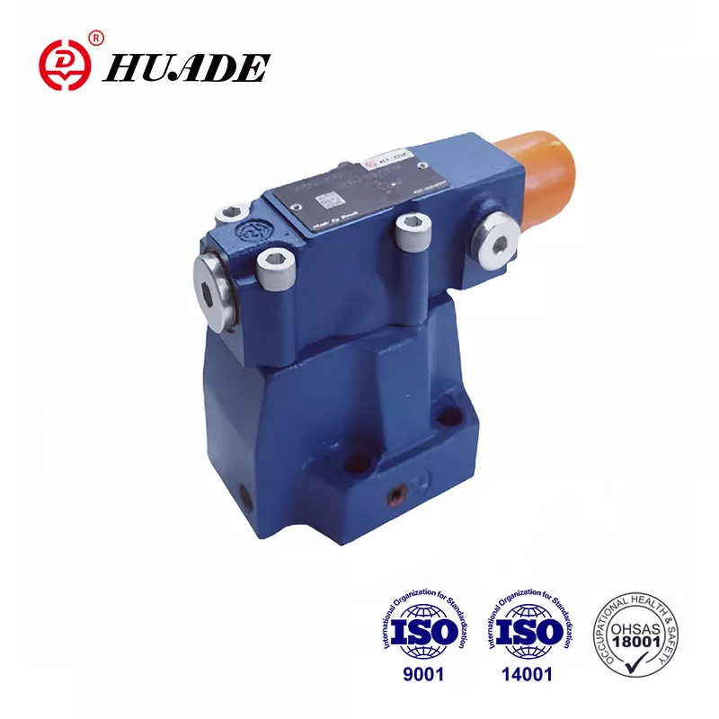
Pressure valves are essential safety devices that control, regulate, and relieve pressure in fluid systems. This comprehensive guide covers pressure relief valves, pressure reducing valves, pressure regulators, and pressure control devices across industrial applications.

Pressure control is critical in any system handling liquids or gases under pressure. Whether you're dealing with steam boilers, hydraulic systems, or water distribution networks, pressure valves serve as the primary safety mechanism preventing catastrophic failures and optimizing system performance.

What Is a Pressure Valve? (Definition and Core Functions)

A pressure valve is an automatic flow control device designed to regulate system pressure by opening to release excess pressure or closing to maintain stable operating conditions. These pressure control valves function as both safety devices and performance optimizers.

Primary Functions:

  • Pressure regulation: Maintains system pressure within predetermined limits
  • Overpressure protection: Prevents equipment damage by releasing excess pressure
  • Flow control: Adjusts fluid flow to optimize system efficiency
  • Safety assurance: Acts as the last line of defense against pressure-related failures

Technical Definition:

According to ASME BPVC Section I, a pressure relief device is "a device actuated by inlet static pressure and designed to open during emergency or abnormal conditions to prevent rise of internal fluid pressure in excess of a specified value."

How Pressure Control Valves Work: Technical Principles

Basic Operating Mechanism

Pressure relief valves operate on the force-balance principle:

Force Balance Equation: F₁(inlet pressure force) = F₂(spring force) + F₃(backpressure force)

Where:

  • F₁ = P₁×A (inlet pressure×effective disc area)
  • F₂ = Spring constant×compression distance
  • F₃ = P₂×A (backpressure×disc area)

Operating Sequence:

  1. Set Pressure: Valve remains closed when system pressure < set pressure
  2. Cracking Pressure: Initial opening occurs at 95-100% of set pressure
  3. Full Lift: Complete opening at 103-110% of set pressure (per API 526)
  4. Reseat Pressure: Valve closes at 85-95% of set pressure (typical blowdown)

Key Technical Parameters:

Parameter Definition Typical Range
Set Pressure Pressure at which valve begins to open 10-6000 psig
Overpressure Pressure above set pressure during discharge 3-10% of set pressure
Blowdown Difference between set and reseat pressure 5-15% of set pressure
Back Pressure Downstream pressure affecting valve performance <10% of set pressure (conventional)
Flow Coefficient (Cv) Valve capacity factor Varies by size/design

Types of Pressure Control Devices: Technical Specifications

1. Pressure Safety Valves (PSV) and Safety Relief Valves (SRV)

Technical Standards: ASME BPVC Section I & VIII, API 520/526

Spring-Loaded Safety Valves

  • Operating Range: 15 psig to 6,000 psig
  • Temperature Range: -320°F to 1,200°F
  • Capacity Range: 1 to 100,000+ SCFM
  • Materials: Carbon steel, stainless steel 316/304, Inconel, Hastelloy
Capacity Calculation (Gas Service): W = CKdP₁KshKv√(M/T)

Where:

  • W = Required capacity (lb/hr)
  • C = Discharge coefficient
  • Kd = Discharge coefficient correction factor
  • P₁ = Set pressure + overpressure (psia)
  • Ksh = Superheat correction factor
  • Kv = Viscosity correction factor
  • M = Molecular weight
  • T = Absolute temperature (°R)

Pilot-Operated Safety Relief Valves (POSRV)

  • Advantages: Tight shutoff, large capacity, reduced chattering
  • Pressure Range: 25 psig to 6,000 psig
  • Accuracy: ±1% of set pressure
  • Applications: High-capacity gas service, critical process applications

2. Pressure Reducing Valves (Pressure Regulators)

Technical Standards: ANSI/ISA 75.01, IEC 60534

Direct-Acting Pressure Regulators

  • Pressure Reduction Ratio: Up to 10:1
  • Accuracy: ±5-10% of set pressure
  • Flow Range: 0.1 to 10,000+ GPM
  • Response Time: 1-5 seconds
Sizing Formula: Cv = Q√(G/(ΔP))

Where:

  • Cv = Flow coefficient
  • Q = Flow rate (GPM)
  • G = Specific gravity
  • ΔP = Pressure drop (psi)

Pilot-Operated Pressure Reducing Valves

  • Pressure Reduction Ratio: Up to 100:1
  • Accuracy: ±1-2% of set pressure
  • Rangeability: 100:1 typical
  • Applications: High-flow, high-pressure reduction applications

3. Back Pressure Regulators and Control Valves

Function: Maintain constant upstream pressure by controlling downstream flow

Technical Specifications:

  • Pressure Range: 5 psig to 6,000 psig
  • Flow Coefficient: 0.1 to 500+ Cv
  • Accuracy: ±2% of set pressure
  • Materials: 316 SS, Hastelloy C-276, Inconel 625

Industrial Applications and Case Studies

Power Generation Industry

Steam Boiler Safety Valves (ASME Section I)

  • Required Capacity: Must discharge all steam generated without exceeding 6% above set pressure
  • Minimum Requirements: One safety valve per boiler; two valves for >500 sq ft heating surface
  • Testing: Manual lifting test every 6 months (high pressure) or quarterly (low pressure)

Case Study: 600 MW Power Plant

  • Main steam pressure: 2,400 psig
  • Safety valve set pressure: 2,465 psig (103% of operating pressure)
  • Required capacity: 4.2 million lb/hr steam
  • Configuration: Multiple 8" x 10" spring-loaded safety valves

Oil & Gas Industry

Pipeline Pressure Safety Systems (API 521)

  • Design Pressure: 1.1 × Maximum allowable operating pressure (MAOP)
  • Safety Valve Sizing: Based on maximum anticipated flow and pressure scenarios
  • Materials: Sour gas service requires NACE MR0175 compliance

Case Study: Natural Gas Pipeline Station

  • Operating pressure: 1,000 psig
  • Safety valve set pressure: 1,100 psig
  • Capacity requirement: 50 MMSCFD
  • Installation: 6" x 8" pilot-operated safety relief valve

Water Treatment and Distribution

Pressure Reducing Valve Stations

  • Inlet Pressure: 150-300 psig (municipal supply)
  • Outlet Pressure: 60-80 psig (distribution network)
  • Flow Range: 500-5,000 GPM
  • Control Accuracy: ±2 psi

Hydraulic Calculation Example:

For a 6" water PRV reducing 200 psig to 75 psig at 2,000 GPM:

  • Required Cv = 2,000√(1.0/125) = 179
  • Select 6" valve with Cv = 185

Chemical and Petrochemical Processing

Reactor Protection Systems

  • Operating Conditions: 500°F, 600 psig
  • Relief Scenarios: Thermal expansion, runaway reactions, cooling failure
  • Materials: Hastelloy C-276 for corrosive service
  • Sizing: Based on worst-case scenario analysis per API 521

Selection Criteria and Engineering Calculations

Performance Parameters

Pressure Ratings (ASME B16.5):

Class Pressure Rating @ 100°F
Class 150 285 psig
Class 300 740 psig
Class 600 1,480 psig
Class 900 2,220 psig
Class 1500 3,705 psig

Temperature Derating:

Pressure ratings must be derated for elevated temperatures according to ASME B16.5 temperature-pressure tables.

Material Selection Guide

Service Body Material Trim Material Spring Material
Water Carbon steel, Bronze 316 SS Music wire
Steam Carbon steel, 316 SS 316 SS, Stellite Inconel X-750
Sour Gas 316 SS, Duplex SS Stellite, Inconel Inconel X-750
Cryogenic 316 SS, 304 SS 316 SS 316 SS
High Temp Carbon steel, Alloy steel Stellite, Inconel Inconel X-750

Sizing Calculations

For Liquid Service (API 520):

Required Area: A = (GPM × √G) / (38.0 × Kd × Kw × Kc × √ΔP)

Where:

  • A = Required effective discharge area (in²)
  • GPM = Required flow rate
  • G = Specific gravity
  • Kd = Discharge coefficient (0.62 for liquids)
  • Kw = Back pressure correction factor
  • Kc = Combination correction factor
  • ΔP = Set pressure + overpressure - back pressure

For Gas/Vapor Service (API 520):

Critical Flow: A = W/(CKdP₁Kb)
Sub-critical Flow: A = 17.9W√(TZ/MKdP₁(P₁-P₂)Kb)

Installation and Maintenance Standards

Installation Requirements (ASME BPVC)

Safety Valve Installation:

  • Inlet piping: Short and direct, avoid elbows within 5 pipe diameters
  • Outlet piping: Sized for 10% back pressure maximum
  • Mounting: Vertical preferred, horizontal acceptable with support
  • Isolation: Block valves prohibited in inlet; acceptable in outlet if locked open

Pressure Reducing Valve Installation:

  • Upstream strainer: 20-mesh minimum for clean service
  • Bypass line: For maintenance and emergency operation
  • Pressure gauges: Upstream and downstream monitoring
  • Relief valve: Downstream protection against overpressure

Maintenance Schedules and Procedures

API 510 Inspection Requirements:

  • Visual inspection: Every 6 months
  • Operational test: Annually
  • Capacity test: Every 5 years
  • Complete overhaul: Every 10 years or per manufacturer recommendations

Testing Procedures:

  • Set Pressure Test: Verify opening pressure within ±3% of setting
  • Seat Leakage Test: API 527 Class IV (5,000 cc/hr maximum)
  • Capacity Test: Verify flow performance meets design requirements
  • Back Pressure Test: Evaluate performance under system conditions

Predictive Maintenance Technologies

Acoustic Emission Testing:
  • Detection: Internal leakage, seat wear, spring fatigue
  • Frequency Range: 20 kHz to 1 MHz
  • Sensitivity: Can detect leaks <0.1 GPM
Vibration Analysis:
  • Applications: Pilot valve chattering, spring resonance
  • Parameters: Amplitude, frequency, phase analysis
  • Trending: Historical data for failure prediction

Compliance Standards and Certifications

ASME Boiler and Pressure Vessel Code

Section I (Power Boilers):

  • Capacity Requirements: Safety valves must prevent pressure rise >6% above set pressure
  • Minimum Safety Valves: One per boiler, two if heating surface >500 sq ft
  • Testing: Manual lifting every 6 months (high pressure) or quarterly (low pressure)

Section VIII (Pressure Vessels):

  • Relief Device Requirements: All pressure vessels require overpressure protection
  • Set Pressure: Not to exceed MAWP of protected equipment
  • Capacity: Based on worst-case scenario per API 521

API Standards Implementation

API 520 (Relief Device Sizing):

  • Scope: Covers conventional, balanced, and pilot-operated relief valves
  • Sizing Methods: Provides calculation procedures for all fluid types
  • Installation: Specifies piping requirements and system integration

API 526 (Flanged Steel Relief Valves):

  • Design Standards: Dimensional requirements, pressure-temperature ratings
  • Materials: Carbon steel, stainless steel specifications
  • Testing: Factory acceptance test requirements

API 527 (Commercial Seat Tightness):

  • Class I: No visible leakage
  • Class II: 40 cc/hr per inch of seat diameter
  • Class III: 300 cc/hr per inch of seat diameter
  • Class IV: 1,400 cc/hr per inch of seat diameter

International Standards

IEC 61511 (Safety Instrumented Systems):

  • SIL Rating: Safety integrity level requirements for pressure protection
  • Proof Testing: Periodic testing to maintain safety function
  • Failure Rate: Maximum allowable failure rates for safety systems

Troubleshooting and Failure Analysis

Common Failure Modes

Premature Opening (Simmer):

Causes:

  • Inlet piping losses exceed 3% of set pressure
  • Vibration or pulsation in system
  • Debris on valve seat
  • Set pressure too close to operating pressure

Solutions:

  • Increase inlet piping size (velocity <30 ft/sec for liquids, <100 ft/sec for gases)
  • Install pulsation dampener
  • Clean valve seat and disc
  • Increase margin between operating and set pressure (>10%)

Failure to Open:

Causes:

  • Spring corrosion or binding
  • Excessive back pressure (>10% of set pressure)
  • Plugged outlet or vent
  • Scale or corrosion on moving parts

Solutions:

  • Replace spring, upgrade materials
  • Reduce back pressure or use balanced valve design
  • Clear obstructions, increase outlet piping size
  • Clean and lubricate, consider different materials

Excessive Leakage:

Causes:

  • Seat damage from debris or corrosion
  • Warped disc from thermal cycling
  • Inadequate seat load (spring fatigue)
  • Chemical attack on sealing surfaces

Solutions:

  • Lap seat and disc surfaces
  • Replace disc, improve thermal design
  • Replace spring, verify set pressure
  • Upgrade materials for chemical compatibility

Diagnostic Techniques

Flow Testing:

  • Purpose: Verify actual vs. design capacity
  • Method: Measure discharge flow at 110% of set pressure
  • Acceptance: ±10% of design capacity per API 527

Metallurgical Analysis:

  • Applications: Failure investigation, material selection
  • Techniques: SEM analysis, hardness testing, corrosion evaluation
  • Results: Root cause determination, material recommendations

Economic Impact and Cost Considerations

Total Cost of Ownership

Initial Investment:

  • Standard Relief Valve: $500-$5,000 depending on size/materials
  • Pilot-Operated Valve: $2,000-$25,000 for complex applications
  • Installation Costs: 25-50% of equipment cost

Operating Costs:

  • Energy Losses: Leaking valves waste 1-5% of system energy
  • Maintenance: $200-$2,000 annually per valve
  • Testing and Certification: $500-$1,500 per valve every 5 years

Failure Costs:

  • Equipment Damage: $50,000-
Related News
X
We use cookies to offer you a better browsing experience, analyze site traffic and personalize content. By using this site, you agree to our use of cookies. Privacy Policy
Reject Accept