When you walk through a factory floor or inspect heavy machinery, you're seeing the visible parts of complex hydraulic systems. But hidden inside these machines are components that make everything work smoothly. The directional control valve WMU is one of these critical components, quietly directing hydraulic fluid to make cylinders extend, retract, and stop exactly when needed.
If you're an engineer selecting components for a new machine, a maintenance technician troubleshooting a stubborn hydraulic issue, or a procurement manager trying to balance quality and cost, understanding the WMU directional control valve can save you time, money, and headaches. This guide breaks down everything you need to know about this workhorse valve in straightforward terms.
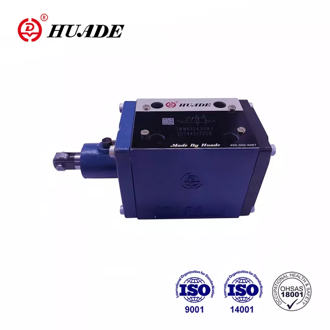
What Makes the WMU Directional Control Valve Different
The directional control valve WMU belongs to a family of hydraulic valves that control where fluid flows in a system. Think of it as a traffic controller for hydraulic oil. When an actuator needs to extend, the valve opens certain pathways. When it needs to retract, the valve switches to different pathways. The WMU accomplishes this through mechanical actuation, which sets it apart from electrically controlled valves.
The "WMU" designation tells you something important about how this valve works. The "W" stands for way or directional, indicating it controls flow direction. The "M" signals mechanical actuation, meaning it's operated by physical movement rather than electrical signals. The "U" often appears alongside "R" (as in WMU/R) to indicate roller plunger operation. This mechanical approach makes the directional control valve WMU particularly reliable in harsh environments where electronics might fail.
Inside the valve, you'll find four main components working together. The valve body houses everything and provides the mounting interface. A roller or lever extends from the body, waiting to be contacted by an external cam or dog attached to your moving equipment. When that contact happens, it pushes a control spool inside the valve body, switching the hydraulic pathways. A return spring then pushes everything back to the starting position once the cam moves away.
How the WMU Actually Works in Your System
Understanding the operation of a directional control valve WMU starts with understanding what happens during a typical machine cycle. Let's say you're running a hydraulic press. As the press ram extends downward, a cam mounted on the ram eventually contacts the roller on your WMU valve. That mechanical contact pushes the valve spool to a new position, which might signal the next stage of your process to begin or trigger a safety function.
The beauty of this mechanical actuation is its simplicity and reliability. There are no solenoid coils to burn out, no electrical connections to corrode, and no pilot pressure required. The directional control valve WMU converts physical position directly into a hydraulic signal. This makes it essentially a hydraulic limit switch, perfect for sequencing operations where one action must complete before the next begins.
The valve connects to your system through standardized mounting patterns. Most WMU valves follow ISO 4401-03-02-0-05 or DIN 24340 Form A standards, which means they mount on what's called an NG6 subplate. This standardization is crucial because it means you can swap valves from different manufacturers without redesigning your whole system. Some larger versions use NG10 mounting, which handles higher flow rates.
When shopping for a directional control valve WMU, you'll see configurations described as "3/2-way" or "4/3-way." These numbers tell you about ports and positions. A 4/3-way valve has four ports (pressure, tank, and two work ports labeled A and B) and three possible positions. The center position is particularly important because it determines what happens when the valve isn't being actuated. Some designs keep everything blocked in the center position, holding your actuator in place. Others allow flow to tank, releasing pressure. The right choice depends on your specific application.
Technical Specifications That Actually Matter
The directional control valve WMU handles impressive specifications that make it suitable for serious industrial work. Maximum pressure ratings typically reach 315 bar, which translates to about 4,569 pounds per square inch. For flow capacity, an NG6 size handles up to 60 liters per minute, while NG10 versions push that to 120 liters per minute. These numbers matter because undersizing a valve creates pressure drops and heat, while oversizing wastes money.
Temperature range is another practical consideration. The directional control valve WMU operates reliably from negative 30 degrees Celsius to positive 80 degrees Celsius. That covers most industrial environments, though you might need special seals for extreme conditions. Speaking of seals, standard valves come with NBR (nitrile rubber) seals, which work well with mineral-based hydraulic oils. If your system uses synthetic fluids or operates in high-temperature conditions, you can specify FKM (Viton) seals instead.
One specification that often gets overlooked is the radial tolerance of the roller plunger. The directional control valve WMU tolerates up to 30 degrees of misalignment between the cam and roller. This flexibility is incredibly valuable during installation and operation. Mounting brackets might not be perfectly aligned, structural components might flex under load, and thermal expansion might shift components slightly. That 30-degree tolerance keeps everything working despite these real-world imperfections.
The valve also handles a wide viscosity range, from 2.8 to 500 square millimeters per second. This means it works with thin hydraulic oils in cold weather and thicker oils at operating temperature. However, there's a tradeoff. Higher viscosity increases internal friction and pressure drop, so you might notice slower response times on cold startups.
Installation Best Practices You Can't Ignore
Installing a directional control valve WMU correctly makes the difference between years of reliable service and frustrating maintenance calls. Start with cleanliness. Before you even unbox the valve, make sure your hydraulic system meets cleanliness standards. ISO 4406 19/17/14 or NAS 1638 Class 9 represents acceptable contamination levels. Flush your system thoroughly before installation, because any dirt that gets into the valve will cause problems later.
The mounting surface matters more than many people realize. Your subplate must be flat, with no burrs or scratches around the port openings. Even small imperfections can create leak paths or prevent proper seating. Torque the mounting bolts to specification using a cross pattern, just like you would with wheel lug nuts on a car. This ensures even pressure distribution and proper sealing.
When positioning the directional control valve WMU on your machine, think about how the cam will contact the roller. The roller can rotate 90 degrees in its housing, giving you flexibility in mounting orientation. However, you want to minimize side loading as much as possible. While the valve tolerates 30 degrees of misalignment, operating at the edge of that tolerance all the time accelerates wear. Aim for direct, square contact between the cam and roller.
Cam design deserves careful attention even though it's technically not part of the valve itself. A poorly designed cam profile can destroy an otherwise excellent directional control valve WMU installation. Avoid steep ramp angles that create shock loading. The cam should contact the roller smoothly, push it through its full travel without excessive force, then release cleanly. Sharp edges or worn cam surfaces cause impact loading that damages both the cam and the valve's internal components.
Common Problems and How to Fix Them
The directional control valve WMU is mechanically robust, but it's not indestructible. Understanding common failure modes helps you troubleshoot problems quickly and prevent failures before they happen.
Spool sticking ranks as the most frequent issue. You'll notice symptoms like slow or incomplete shifting, where the actuator doesn't quite reach the end of its stroke or hesitates during movement. The root cause is usually contamination. Dirt particles get trapped between the spool and bore, creating friction that the actuation force can't overcome. Sometimes you'll also see spool sticking from side loading, where misalignment causes the spool to bind against one side of the bore. The solution involves improving filtration, flushing the system, and checking alignment. In severe cases, you might need to replace the valve entirely if the bore has been scored.
Roller and plunger wear manifests as inconsistent triggering. The directional control valve WMU might work fine for dozens of cycles, then suddenly fail to shift. Or you might notice increasing actuation force required. This happens because the contact surfaces between the cam and roller wear down over time, especially without adequate lubrication. Metal particles from this wear then circulate through your system, accelerating wear on other components. Prevention involves ensuring your hydraulic fluid maintains a proper lubricating film and checking alignment regularly. Once significant wear occurs, replacement is usually more cost-effective than trying to repair.
Spring failure is less common but more dramatic. If the return spring breaks or becomes jammed, the directional control valve WMU gets stuck in the actuated position and won't return to neutral. Your machine cycle stops dead, often in an awkward or unsafe position. This failure mode is why many systems include redundant safety features rather than relying solely on the valve. Regular inspection helps catch spring fatigue before complete failure, and many maintenance programs include preventive spring replacement on a time or cycle basis.
Hydraulic shock creates problems that might not be immediately obvious. When the directional control valve WMU shifts positions suddenly, it creates transient pressure spikes in the lines. These spikes generate noise, accelerate component fatigue, and can cause cavitation damage. You'll hear it as a banging or hammering sound in your hydraulic lines. The solution involves adding throttle valves or shock dampeners in the pressure line to slow down flow changes. This does create some additional pressure drop, so you need to account for that in your system design.
Maintenance Strategies That Actually Work
Keeping a directional control valve WMU running reliably doesn't require exotic tools or advanced training, but it does require consistency. The most important maintenance task is also the simplest: maintain clean hydraulic fluid. Change your fluid according to the manufacturer's recommendations, not just when it looks dirty. Hydraulic oil degrades chemically over time even if it still appears clean. Use filters rated for your application and change them on schedule.
Monitor your system pressure regularly. A sudden drop in pressure might indicate internal leakage in the valve. Gradual pressure loss over weeks or months suggests seal degradation. Catching these trends early lets you schedule maintenance during planned downtime rather than dealing with an emergency shutdown.
Pay attention to unusual noises. The directional control valve WMU should operate quietly except for a slight click as it shifts positions. Grinding, squealing, or banging sounds all indicate problems. Grinding usually means contamination, squealing points to insufficient lubrication, and banging signals hydraulic shock.
Check the cam and roller condition during routine inspections. Look for signs of wear, scoring, or deformation. A worn cam surface might still trigger the valve but creates impact loading that accelerates internal wear. The roller should rotate freely on its bearing. If it's frozen in place, the cam drags across the roller surface rather than rolling smoothly, creating excessive heat and wear.
Keep detailed maintenance records. Note when you change filters, when you flush the system, and any symptoms you observe. Patterns often emerge that help you predict problems before they cause failures. For example, if you notice spool sticking tends to occur after about 10,000 cycles, you can plan preventive replacement at 8,000 cycles.
OEM vs Compatible Alternatives: Making the Right Choice
The market for directional control valves offers both original equipment manufacturer products and compatible alternatives. Bosch Rexroth sets the standard as the primary OEM for WMU valves, with decades of proven performance across industries. Their valves appear in applications ranging from construction equipment to chemical processing plants, aerospace ground support equipment to marine systems.
Compatible manufacturers like Huade Hydraulic produce valves that meet the same standards and offer interchangeable mounting. These alternatives typically cost 20 to 30 percent less than OEM products, which sounds attractive when you're managing a budget. The real question is whether that cost savings makes sense for your specific application.
For mission-critical systems where failure creates safety hazards or extremely expensive downtime, OEM valves make sense. Think about a directional control valve WMU controlling steering on a marine vessel or positioning heavy loads in a steel mill. The premium you pay for OEM quality is insurance against the catastrophic costs of failure. OEM valves typically show better performance in high-vibration environments and maintain their specifications through more cycles.
For less critical applications with lower duty cycles, compatible valves can optimize your total cost of ownership. A directional control valve WMU sequencing a low-speed press in a job shop doesn't face the same demands as one in continuous production. The cost savings from compatible valves let you stock spares or upgrade other system components. Just make sure you're buying from reputable suppliers who actually meet the standards they claim and can provide documentation.
A smart strategy involves dual sourcing. Use OEM directional control valves in critical paths where failure stops production or creates safety issues. Specify compatible valves for secondary functions where you can afford slightly reduced reliability. This approach balances risk and cost across your entire facility.
Real-World Applications Where WMU Excels
The directional control valve WMU shines in applications where mechanical position sensing is required and electrical components would be problematic. Machine tools provide a perfect example. As a milling machine table travels to its end position, a cam on the table contacts the WMU valve, triggering the next operation. The mechanical nature of this interaction works reliably even with coolant spray, metal chips, and temperature variations that would challenge electrical sensors.
Punch presses and stamping equipment use directional control valves extensively for sequencing operations. The press ram carries cams that trigger valves at specific positions during the stroke. One valve might signal when the die is closed for a holding circuit. Another might trigger part ejection. A third might control a safety gate. These mechanical interlocks provide reliable sequencing without complex programming or electrical panels that add cost and failure points.
Metallurgical equipment operates in some of the harshest industrial environments imaginable. Rolling mills, forges, and heat treatment systems combine high temperatures, heavy contamination, and intense vibration. The directional control valve WMU handles these conditions better than electrically actuated alternatives. The mechanical actuation doesn't care about electromagnetic interference, dust, or temperature extremes that would disable electronic components.
Marine and offshore applications value the reliability of mechanical actuation. Salt spray, moisture, and constant vibration plague electrical systems on ships and platforms. A directional control valve WMU controlling deck machinery or steering systems provides dependable operation without corrosion concerns. The mechanical nature also simplifies maintenance, since you don't need specialized electronic diagnostic equipment.
Material handling systems use WMU valves for limit stops and position sensing. A hydraulic lift cylinder extends until it reaches a preset position, where a cam triggers the valve to stop movement or signal readiness for the next operation. This mechanical feedback is immediate and doesn't depend on timing circuits or sensors that might drift out of calibration.
System Design Considerations for Optimal Performance
Integrating a directional control valve WMU into your hydraulic system requires thinking beyond just the valve itself. The valve interacts with every other component, so system-level design choices affect performance and reliability.
Pressure line design matters more than many engineers realize. When the directional control valve WMU shifts positions, it creates flow transients that can spike pressure throughout the system. These pressure spikes stress every component and create the banging noises often heard in hydraulic systems. Adding a small orifice or throttle valve in the pressure line damps these transients. The tradeoff is additional pressure drop and some heat generation, but the reduction in shock loading extends component life significantly.
Flow capacity needs careful matching. The directional control valve WMU comes in different sizes precisely because one size doesn't fit all applications. Undersizing creates excessive pressure drop, which wastes power and generates heat. Your actuators respond slowly, and the valve runs hot. Oversizing seems safer but costs more money than necessary and can actually create control problems in some applications. Calculate your maximum flow requirements carefully and select the next standard size up.
Filtration deserves more attention than it typically receives. The directional control valve WMU has tight clearances between the spool and bore, typically measured in microns. Particles smaller than what standard system filters catch can still cause problems. Consider adding a high-efficiency filter immediately upstream of critical valves. The additional pressure drop is minimal, and the protection against contamination pays off in extended component life.
Mounting location affects both performance and maintenance access. Placing the directional control valve WMU where you can easily see it during operation helps with troubleshooting. Being able to visually confirm that the cam is contacting the roller properly saves hours of head-scratching when circuits don't work as expected. At the same time, try to minimize plumbing runs between the valve and actuators it controls. Every extra foot of hose or tube adds pressure drop, potential leak points, and trapped fluid volume that slows response.
The Future of Mechanical Directional Control
Looking at broader trends in hydraulic systems, you might wonder about the long-term place of the directional control valve WMU. Electro-hydraulic proportional valves and electronic controls offer sophisticated capabilities that mechanical valves can't match. Yet mechanical actuation isn't becoming obsolete anytime soon.
The reliability advantage of mechanical systems remains compelling for certain applications. When failure isn't an option and simplicity matters, direct mechanical actuation wins. Industries with harsh environments continue to choose the directional control valve WMU because it works when electronics won't. There's no software to update, no firmware to corrupt, and no sensors to recalibrate.
Cost considerations also favor mechanical valves for many applications. A basic directional control valve WMU costs a fraction of what you'd pay for an equivalent electronic system. When you factor in installation time, programming, and ongoing maintenance, the total cost difference becomes even more pronounced. For applications where simple on-off control is sufficient, spending extra money for proportional control makes little sense.
Standardization continues to improve, making the directional control valve WMU more versatile. As manufacturers adopt common mounting patterns and port configurations, you gain more freedom to mix and match components from different suppliers. This competition drives both innovation and cost reduction, benefiting end users.
Making Your Selection Decision
Choosing the right directional control valve WMU for your application comes down to matching specifications to requirements while considering total cost of ownership. Start by clearly defining what you need the valve to do. What pressure and flow rates must it handle? What environmental conditions will it face? How many cycles per day will it operate through? What's the consequence of failure?
With requirements defined, evaluate options from both OEM and compatible manufacturers. Request complete technical documentation, not just marketing literature. Look for actual performance curves, dimensional drawings, and maintenance recommendations. Be wary of suppliers who can't provide detailed specifications or who make claims that seem too good to be true.
Consider the total cost picture beyond just purchase price. A cheaper valve that requires replacement twice as often doesn't save money. Factor in installation time, spare parts availability, technical support quality, and potential downtime costs. Sometimes paying more upfront for an OEM directional control valve WMU makes perfect economic sense. Other times, a compatible alternative optimizes value.
Don't forget about support and service. Can you easily get replacement parts? Does the manufacturer provide technical support if you have questions? Are there local distributors who stock the valves and can deliver quickly when you need emergency replacement? These factors often matter more than small price differences.
The directional control valve WMU represents proven technology that continues to serve industrial hydraulics well. Its mechanical simplicity provides reliability in demanding environments where more sophisticated alternatives struggle. By understanding how these valves work, what specifications matter, and how to maintain them properly, you can deploy them effectively in your systems and keep them running for years. Whether you're designing a new machine or maintaining existing equipment, the WMU directional control valve deserves consideration as a robust, cost-effective solution for hydraulic flow control.