When industrial machinery needs to change direction reliably, the directional control valve WMR series offers a solution that's been trusted for decades. These mechanically operated valves control the flow of hydraulic fluid in industrial systems, determining when cylinders extend or retract and when motors spin forward or backward.
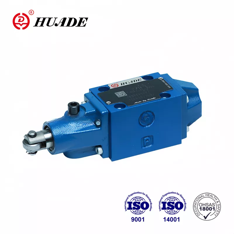
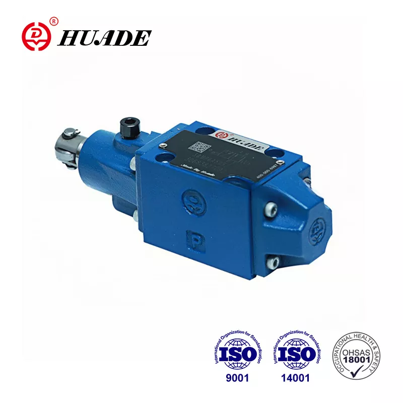
The WMR valve stands out because it works through pure mechanical action. A roller or plunger gets pushed by a cam or moving part, which shifts the internal spool and redirects the oil flow. This direct physical connection means the valve responds to actual machine position rather than electrical signals, making it ideal for applications where mechanical reliability matters most.
Understanding the Basic Function
The directional control valve WMR operates as a spool valve mounted on a subplate. When nothing pushes the roller, return springs hold the spool in its neutral position. Once an external cam or mechanical component presses against the roller plunger, the spool slides inside the valve body and connects different ports together. This action redirects hydraulic fluid to drive actuators in the desired direction.
This design philosophy creates a direct link between physical position and hydraulic action. Machine tools, cranes, and material handling equipment use this principle to ensure movements happen in the correct sequence. The valve cannot switch until something physically moves the roller, which provides inherent safety in many applications.
Technical Specifications That Matter
The directional control valve WMR series comes in two main sizes following ISO 4401 standards. The NG6 size handles flows up to 60 liters per minute and pressure up to 315 bar at the P, A, and B ports. The NG10 size offers similar pressure ratings with higher flow capacity. These specifications allow the valve to work in demanding industrial environments.
Operating temperature ranges from negative 20 degrees Celsius to positive 80 degrees Celsius with standard NBR seals. The valve accepts hydraulic fluids with viscosity between 2.8 and 500 square millimeters per second. Maintaining fluid cleanliness at ISO 4406 Class 20/18/15 or better helps prevent internal wear and extends service life.
One limitation requires attention during system design. The T port, which returns fluid to the tank, has a standard pressure limit of 60 bar. While the main working ports handle 315 bar easily, exceeding 60 bar at the T port can damage seals or cause leakage. Some high-specification variants increase this limit to 210 bar for applications with higher back pressure.
Different Configurations for Different Needs
The directional control valve WMR series offers multiple spool configurations, typically shown as hydraulic symbols. A four-port, three-position valve might hold all ports blocked in neutral, or it might connect certain ports to tank. The symbol codes like C, E, J, L, and M indicate which ports connect in each position. Manufacturers offer about 19 different symbol variations to match different circuit requirements.
Two-position valves provide simpler on-off control. Three-position valves add a neutral state that can block flow, allow free movement, or create other conditions depending on the spool design. Choosing the right configuration depends on whether cylinders need to hold their position when the valve returns to neutral or if they should float freely.
Manufacturers and Model Variations
Bosch Rexroth produces the original WMR series as part of their Hydronorma product family. Their NG6 size 5X series includes various roller arrangements and mounting options. The valves mount on standardized subplates following CETOP patterns, which simplifies replacement and allows mixing components from different manufacturers.
Hengli Hydraulics offers the WMR/U10 series for NG10 applications. Their L3X series provides 19 symbol options with both R-type and U-type roller configurations. This variety helps engineers select the exact roller position and actuation direction needed for their specific machinery layout.
Other suppliers like PONAR Wadowice and Leader Hydraulics manufacture compatible valves. The standardization under ISO 4401 means these valves can physically interchange, though designers should verify that pressure ratings, flow capacities, and spool configurations match their application needs.
Installation Requirements
Proper installation of a directional control valve WMR starts with surface preparation. The mounting surface on the subplate must meet flatness specifications of 0.01 per 100 millimeters with a maximum surface roughness of Rz 4. Any irregularities can create leak paths around the valve base.
Four M6 by 40 millimeter socket head cap screws secure the valve to the subplate. Tightening these bolts to 9 newton meters with a tolerance of plus or minus 15 percent provides adequate clamping force without distorting the valve body. Cross-tightening in a diagonal pattern ensures even pressure distribution.
The hydraulic system must use proper filtration before connecting to the directional control valve WMR. Installing filters that maintain ISO 4406 Class 20/18/15 cleanliness protects the close clearances between the spool and body. Even small particles can scratch these surfaces, causing internal leakage or sticking.
Real-World Applications
Machine tools use the directional control valve WMR for tool changing sequences and work clamping operations. As the machine spindle or tool changer moves to specific positions, cams activate the roller and trigger hydraulic movements. This ensures the correct sequence happens automatically without electronic controls.
Mining and metallurgical equipment relies on these valves for conveyor positioning and gate control. The harsh environments in these industries make mechanical actuation attractive because there are no electrical connections to corrode or fail. Dust and moisture that would destroy electronic sensors have minimal impact on a simple roller and cam arrangement.
Lift platforms and scissor lifts incorporate WMR valves in safety systems. The roller position can indicate whether safety bars are in place or if the platform has reached certain heights. This physical verification adds redundancy to safety circuits and complies with regulations requiring mechanical interlocks.
Maintenance and Troubleshooting
External leakage around the mounting surface usually indicates damaged O-rings or an improperly torqued valve. Inspecting and replacing the mounting gasket solves most external leak problems. Verifying that the mounting surface remains flat and undamaged prevents recurrence.
Internal leakage shows up as actuators drifting slowly when the valve should hold them in position. This often results from contaminated fluid wearing the spool and bore. Checking fluid cleanliness and replacing filters addresses the root cause. In severe cases, the valve may need replacement if wear exceeds acceptable limits.
Sticky or sluggish operation happens when the spool does not move freely inside the bore. Contamination again tops the list of causes, but operating outside the specified temperature or viscosity ranges also creates problems. Ensuring the hydraulic fluid stays within specifications prevents most operational issues with the directional control valve WMR.
Comparing with Other Valve Types
The WMM series uses a manual lever instead of a roller for actuation. Operators manually move the lever to change valve position, which works well for controls that people operate directly. The WMD series replaces the lever with a rotary knob, offering a more compact manual control option.
Electrically operated solenoid valves provide remote control but require electrical power and control signals. These valves switch faster than mechanical types but introduce potential failure points through wiring, solenoids, and electronic controllers. The directional control valve WMR eliminates these concerns in applications where mechanical actuation makes sense.
Pilot-operated valves use hydraulic pressure to shift larger spools, allowing control of higher flows with smaller actuating forces. These valves cost more and add complexity compared to the direct-acting WMR design. For applications within the flow and pressure capabilities of the WMR, the simpler design often proves more reliable and economical.
Pressure Management Considerations
While the P, A, and B ports handle 315 bar safely, the T port limitation requires system design attention. Any restriction in the tank line or use of a pressurized reservoir raises pressure at the T port. Back pressure from other valves sharing the same tank line also affects this port.
Installing a separate tank line for valves with significant return flow helps manage T port pressure. Some designers use a dedicated low-pressure return manifold that connects directly to the tank with minimal restriction. For systems where higher T port pressure is unavoidable, specifying high-pressure variants of the directional control valve WMR prevents premature seal failure.
Check valves or restrictors in certain circuit locations can unexpectedly create pressure at the T port. Careful circuit analysis during design identifies these situations. Pressure gauges at the T port during commissioning verify that actual conditions stay within specifications.
Flow Control Integration
The directional control valve WMR switches flow direction but does not control flow rate directly. Most applications require additional flow control to regulate actuator speed. Needle valves or pressure-compensated flow controls install either in the circuit or directly in the valve ports.
Some WMR models accept threaded cartridge restrictors that install directly into the P port. These B08, B10, or B12 size plugs provide simple flow limitation and damping of pressure spikes. The integrated design saves space and reduces the number of separate components in the hydraulic manifold.
Meter-in flow control restricts fluid entering the actuator, while meter-out control restricts return flow. The choice depends on the load characteristics and desired control quality. The directional control valve WMR accommodates either approach through proper circuit design around the valve.
Market Considerations for 2025
Supply chain challenges continue affecting hydraulic component availability. Lead times for specialized WMR configurations can extend several months, with some manufacturers quoting delivery dates into September 2025. Planning ahead and maintaining strategic inventory helps avoid production delays.
Pricing for standard NG6 configurations starts around 800 US dollars from major manufacturers. The secondary market offers alternatives, with used valves sometimes available in the 150 to 200 dollar range. However, buying used valves requires careful inspection to verify internal condition and avoid premature failure.
Multi-sourcing strategies that include both premium brands like Bosch Rexroth and compatible alternatives from manufacturers like Hengli provide supply flexibility. The ISO 4401 standardization means switching between brands remains feasible if specifications match. Maintaining approved vendor lists for multiple suppliers reduces risk in the current market environment.
The Role in Modern Automation
As factories add more sensors, controllers, and network connectivity, the simple mechanical directional control valve WMR offers strategic advantages. It cannot be hacked, requires no software updates, and fails in predictable ways. This reliability becomes valuable for safety-critical functions that need mechanical backup.
European regulations like the Cyber Resilience Act focus on digital product security. Purely mechanical components like the WMR valve fall outside these requirements, simplifying compliance for machinery manufacturers. The valve provides a secure foundation layer that does not introduce cybersecurity vulnerabilities into the system.
Energy efficiency concerns drive interest in optimizing hydraulic systems. While the directional control valve WMR itself does not save energy, its reliability and low internal leakage contribute to overall system efficiency. Properly sized valves with appropriate flow ratings minimize pressure drops and wasted heat generation.
Selecting the Right Configuration
Choosing a directional control valve WMR starts with understanding the application requirements. Maximum flow rate and pressure determine whether NG6 or NG10 sizing is appropriate. The actuator type and desired neutral position behavior dictate the symbol configuration needed.
Roller positioning affects how the valve integrates with the mechanical system. R-type rollers mount on one side while U-type rollers mount on another, allowing flexibility in cam placement. The actuation force required and available cam geometry influence this choice.
Seal material selection depends on fluid type and temperature extremes. Standard NBR seals work with petroleum-based hydraulic oil in typical industrial temperature ranges. High-temperature applications or synthetic fluids may require FKM seals that tolerate different conditions. Verifying chemical compatibility prevents seal swelling or deterioration.
Documentation and Support Resources
Manufacturers provide detailed technical documentation for the directional control valve WMR through their websites. Data sheets list exact specifications, dimensions, and ordering codes. Installation manuals cover mounting procedures and torque values in detail.
CAD models in various formats help with machine design and manifold layout. These 3D representations show exact valve envelopes and port locations, allowing interference checking before physical prototyping. Most manufacturers offer models in STEP or IGES formats that import into common design software.
Application engineering support helps solve complex circuit design questions. Manufacturers maintain technical teams who can recommend specific configurations for unusual applications or troubleshoot problems in existing systems. Taking advantage of these resources during the design phase prevents costly mistakes and redesigns.
Final Considerations
The directional control valve WMR serves applications where mechanical position control and reliable switching matter more than electronic sophistication. Its proven design handles demanding conditions in mining, metalworking, and material handling without the vulnerabilities of electronic controls. Understanding its capabilities and limitations allows engineers to apply it effectively.
Proper fluid management extends valve life significantly. Maintaining cleanliness standards, operating within specified temperature and viscosity ranges, and managing T port pressure prevents most failure modes. These simple precautions make the directional control valve WMR a long-lasting component that provides decades of service.
In a world pushing toward digital transformation, the WMR valve proves that mechanical solutions still have important roles. Its inability to be hacked or remotely manipulated provides inherent security. The physical connection between machine position and hydraulic action creates predictable behavior that safety systems can depend on. For these reasons, the directional control valve WMR remains relevant in modern industrial hydraulics.