When you're working with hydraulic systems that need reliable manual control, the directional control valve WMM 6 stands out as a practical choice. This valve, manufactured by Bosch Rexroth, has been serving industries worldwide for decades. It's designed to control the flow of hydraulic fluid with precision, helping operators manage everything from industrial machinery to mobile equipment.
The WMM 6 belongs to a family of manually operated directional valves that follow international standards. What makes this valve particularly useful is its straightforward operation combined with robust construction. Engineers and technicians appreciate how it handles medium to high-pressure applications without requiring complex electrical systems or external power sources.
Understanding the Basics of WMM 6 Design
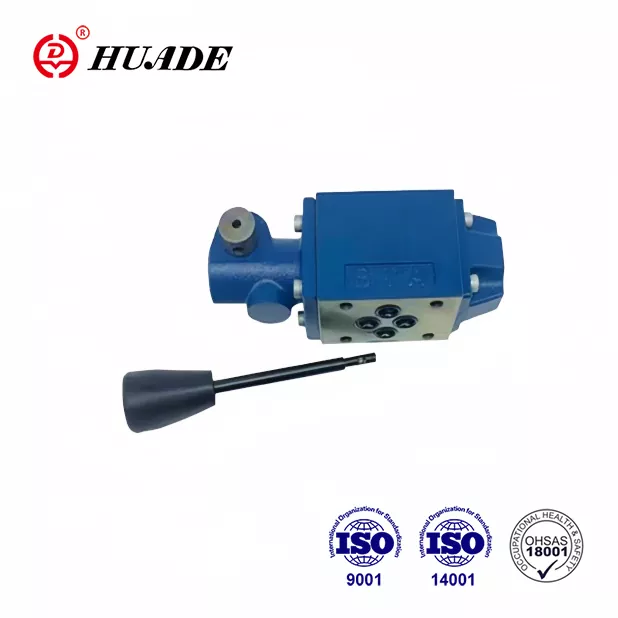
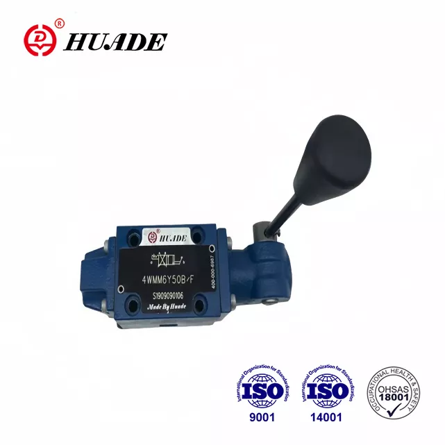
The directional control valve WMM 6 operates through a sliding spool mechanism inside a precision-machined housing. When you move the manual lever, the spool shifts position, opening and closing specific pathways for hydraulic fluid. This direct operation method means there's no delay between your input and the valve's response.
The valve body mounts directly onto a subplate following the CETOP 3 standard, also known as NG6 or ISO 4401-03 interface. This standardization makes installation straightforward and allows the valve to fit into existing hydraulic systems without custom modifications. The housing is typically made from zinc-plated steel, providing excellent corrosion resistance even in demanding environments.
Inside the valve, you'll find carefully designed spools with sealing lands that minimize internal leakage. These spools come in different configurations, each identified by a specific symbol letter. The spring-return mechanism ensures the valve returns to its neutral position when you release the lever, which is essential for safe operation.
Technical Specifications That Matter
The directional control valve WMM 6 handles pressures up to 315 bar on its main ports, with a maximum flow capacity of 60 liters per minute. These specifications make it suitable for medium-sized hydraulic cylinders and motors. The tank port can handle up to 160 bar, which is adequate for most standard applications.
Operating temperature range extends from minus 30 to plus 80 degrees Celsius when using standard NBR seals. For applications involving higher temperatures or chemical-resistant fluids, the valve is available with FKM seals coded as variant V. The valve maintains performance across a wide viscosity range, from 2.8 to 500 square millimeters per second, though optimal performance occurs around 46 mm²/s using standard hydraulic oils like HLP46.
The complete valve assembly weighs approximately 1.4 kilograms for the three-position version and 1.6 kilograms when equipped with a ratchet detent mechanism. The manual lever requires about 20 to 30 newtons of force to operate, depending on system pressure and spool configuration. This force level ensures positive control without causing operator fatigue during extended use.
Spool Symbols and Flow Path Options
Understanding spool symbols is crucial when selecting a directional control valve WMM 6 for your application. Each symbol represents a specific flow path configuration that determines how the valve behaves in different positions. The symbol is marked directly on the valve body for easy identification.
Symbol E represents a closed-center configuration where all ports are blocked in the neutral position. This design is ideal when you need to hold a hydraulic cylinder in position without drift. When you move the lever to position A, pressure flows to port A while port B connects to tank, and vice versa for position B.
Symbol M features an open-center design where ports A and B connect to tank in neutral position while the pressure port remains blocked. This configuration is common in directional switching applications where you want minimal pressure buildup during neutral. The flow capacity tends to be higher with this symbol compared to others.
Symbol C offers another popular configuration where pressure connects to tank in neutral while work ports A and B are blocked. This design helps prevent motor creep in applications where maintaining position is less critical than ensuring the pump can unload. Symbol J provides a tandem center where pressure partially connects to both tank and work ports, useful in specific applications requiring reduced pressure during neutral.
Real-World Applications and Industry Use
The directional control valve WMM 6 finds widespread use in manufacturing facilities where manual control of hydraulic functions is necessary. Injection molding machines often incorporate these valves for mold opening and closing operations. The direct mechanical control provides operators with tactile feedback that electronic controls cannot match.
Mobile equipment represents another major application area. Agricultural machinery, construction equipment, and material handling vehicles use the WMM 6 for functions that benefit from manual override capability. The valve's robust construction withstands vibration and temperature variations common in mobile environments.
In hazardous locations, the WMM 6 XC variant offers explosion-proof operation compliant with ATEX directives. This makes the valve suitable for oil and gas operations, mining environments, and chemical processing facilities where flammable atmospheres may be present. The XC version maintains surface temperatures below 100 degrees Celsius and meets requirements for Group II Category 2G/D equipment.
Maintenance workshops and test benches frequently employ the directional control valve WMM 6 for manual control during setup and troubleshooting procedures. The valve's simple operation and reliable performance make it ideal for applications where operators need precise control without complex programming or setup procedures.
Comparing WMM 6 With Alternative Solutions
Within the Bosch Rexroth product range, the directional control valve WMM 6 sits alongside other manually operated valves that serve similar purposes but with different actuation methods. The WMR 6 series uses roller or plunger actuation, making it suitable for cam-operated sequential control. The WMD 6 variant features rotary knob operation, offering more compact installation in space-constrained applications.
For remote operation requirements, the WMU 6 series provides hydraulic pilot control instead of direct manual actuation. This allows valve operation from a distance using small pilot valves. However, this adds system complexity and requires a pilot pressure source, which the basic WMM 6 does not need.
Solenoid-operated valves like the 4WE 6 series offer automation benefits and integration with electronic control systems. These electrically operated directional control valves respond to PLC signals and enable complex sequencing. However, they require electrical power and typically cost about 20 percent more than the manual WMM 6. The manual valve provides a reliable backup in case of power failure.
The directional control valve WMM 6 delivers cost-effectiveness for applications where manual operation is acceptable or preferred. Its simplicity translates to lower initial cost, reduced maintenance requirements, and excellent long-term reliability. The absence of electrical components eliminates concerns about electromagnetic interference or electrical failures.
Installation Guidelines and Best Practices
Proper installation of the directional control valve WMM 6 begins with preparing the mounting subplate surface. The surface must be flat, clean, and free from scratches or damage that could cause leakage. Apply a thin film of hydraulic oil to the O-ring seals before installation to prevent damage during assembly.
Mount the valve using four M5 socket head screws with a tightening torque of 10 newton-meters. Follow a diagonal tightening pattern to ensure even pressure distribution across the mounting surface. The valve can be installed in any orientation since it operates on sliding spool principles rather than gravity-dependent mechanisms.
System filtration plays a critical role in valve longevity. Install filters capable of achieving ISO 4406 cleanliness code 20/18/15 or better, which corresponds to approximately 25-micron filtration. Contamination is the leading cause of premature wear in directional control valves, so maintaining proper fluid cleanliness cannot be overemphasized.
Avoid using the directional control valve WMM 6 in predominantly single-direction flow applications if possible. Unbalanced flow forces can cause accelerated wear and may require installation of pressure compensation devices. When single-direction operation is unavoidable, consider adding throttle inserts at the pressure port to reduce flow forces and minimize spool deflection.
Maintenance Considerations and Troubleshooting
Regular inspection of the directional control valve WMM 6 should include checking for external leakage around the housing and port connections. Small amounts of seepage may indicate worn O-rings that need replacement. Most seal kits are readily available and can be installed without specialized tools.
The valve spool should move smoothly through its full range of motion without binding or excessive force. If operating force increases noticeably, this may indicate contamination in the spool bore or wear on the spool lands. Internal inspection requires removing the valve from the system and disassembling according to manufacturer guidelines.
When operating with fire-resistant fluids like HFC types, expect reduced seal life compared to mineral oil operation. The directional control valve WMM 6 remains compatible with these fluids, but maintenance intervals should be shortened by 30 to 50 percent. Ensure adequate preload on the tank port when using HFC fluids to maintain proper sealing.
For applications in explosive atmospheres using the XC variant, periodic verification of surface temperature compliance is recommended. Maintain detailed service records showing compliance with ATEX requirements. Any modifications or repairs must preserve the explosion-proof characteristics of the valve assembly.
Selecting the Right Configuration for Your Needs
Choosing the appropriate directional control valve WMM 6 model requires careful consideration of your application requirements. Start by determining the necessary flow capacity and maximum operating pressure. While the valve handles up to 60 liters per minute and 315 bar, operating below maximum ratings typically extends service life.
Next, select the spool symbol that matches your functional requirements. If you need to hold a load in position, symbol E provides the lowest internal leakage. For applications where the pump must unload in neutral, symbol C or M might be more appropriate. Review the flow path diagrams carefully to ensure the selected symbol provides the desired circuit behavior.
Decide whether a detent mechanism is necessary for your application. The optional ratchet detent holds the lever in the selected position without requiring continuous operator input. This feature proves valuable when an actuator must remain extended or retracted for extended periods, though it does slightly reduce maximum flow capacity.
Consider the operating environment when specifying seal material. Standard NBR seals work well for most applications using mineral oil-based hydraulic fluids. The V-coded FKM seals offer better resistance to high temperatures and certain synthetic fluids. For explosive atmosphere applications, specify the XC variant with appropriate ATEX certification documentation.
Fluid Compatibility and System Integration
The directional control valve WMM 6 operates successfully with a wide range of hydraulic fluids. Standard mineral oils meeting DIN 51524 specifications provide excellent service life and performance. Biodegradable hydraulic fluids in the HETG and HEES categories are also compatible, making the valve suitable for environmentally sensitive applications.
When using water-glycol fluids classified as HFC, be aware that component life may be reduced compared to mineral oil operation. These fluids offer fire resistance benefits that outweigh the maintenance considerations in many applications. Water-based fluids require careful attention to system design to prevent cavitation and ensure adequate lubrication of internal components.
System designers should consider pressure drop through the directional control valve WMM 6 when calculating pump requirements. At rated flow of 60 liters per minute, expect pressure drops ranging from 5 to 15 bar depending on spool symbol and flow direction. This pressure loss must be factored into overall system efficiency calculations.
The valve integrates easily with standard hydraulic components including pumps, cylinders, motors, and accumulators. Its CETOP mounting interface ensures compatibility with subplates from various manufacturers. When replacing older valves, verify that port sizes and mounting patterns match to avoid installation issues.
Future Developments and Industry Trends
While the directional control valve WMM 6 represents proven technology, ongoing developments continue to enhance its capabilities. Some manufacturers are exploring sensor integration that would provide position feedback without compromising the valve's inherent simplicity. Such developments could enable condition monitoring while maintaining manual operation as the primary control method.
The trend toward Industry 4.0 connectivity affects even traditional components like manual directional valves. Future versions might incorporate wireless monitoring of cycle counts, operating temperature, and pressure conditions. This data could support predictive maintenance strategies without requiring redesign of existing hydraulic systems.
Environmental regulations continue driving demand for biodegradable hydraulic fluids and reduced energy consumption. The directional control valve WMM 6 already supports most environmentally friendly fluids, positioning it well for these requirements. Ongoing seal material development should further improve compatibility with emerging fluid formulations.
Despite advances in electronic control, manual valves maintain relevance for backup systems, emergency operations, and applications where simplicity and reliability outweigh automation benefits. The directional control valve WMM 6 will likely continue serving these roles while gradually incorporating monitoring capabilities that enhance rather than replace its core manual operation.
Procurement and Availability Considerations
The directional control valve WMM 6 is widely available through authorized Bosch Rexroth distributors worldwide. Lead times typically range from immediate availability for common configurations to several weeks for specialized variants. When planning system installations or maintenance, account for procurement time, especially for less common spool symbols or explosion-proof versions.
Pricing varies based on configuration, with basic models starting around 100 to 300 euros for single-unit purchases. Volume pricing reduces per-unit costs significantly for projects requiring multiple valves. Authorized distributors can provide detailed quotes based on specific model codes and quantities.
When sourcing the directional control valve WMM 6, verify that suppliers provide genuine Bosch Rexroth products with appropriate documentation. Counterfeit hydraulic components represent a significant concern in some markets, potentially compromising system safety and performance. Request certificates of conformity and verify part numbers against official catalogs.
Technical support availability should factor into supplier selection. Distributors with in-house hydraulic expertise can assist with application questions, troubleshooting, and system design support. This value-added service often proves more important than minor price differences, especially for critical applications or complex systems.
Conclusion
The directional control valve WMM 6 delivers reliable manual control for hydraulic systems across diverse industries and applications. Its proven design, standardized interface, and robust construction make it a practical choice when direct operator control is desired or required. Understanding the technical specifications, configuration options, and proper application guidelines ensures successful integration into your hydraulic system.
Whether you're designing new equipment, upgrading existing systems, or specifying replacement components, the WMM 6 merits consideration for manual directional control applications. Its combination of performance, reliability, and cost-effectiveness has established it as a standard solution in the hydraulic industry. With proper selection, installation, and maintenance, this valve provides years of trouble-free service in demanding hydraulic applications.