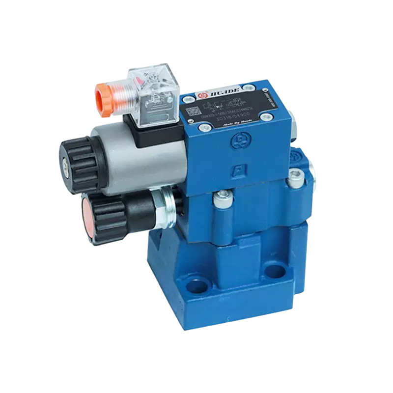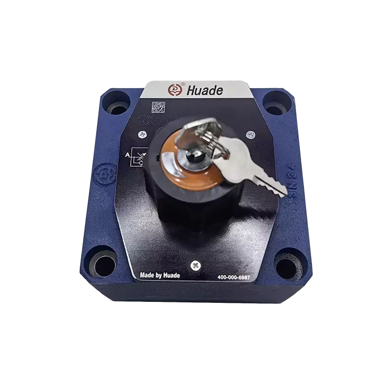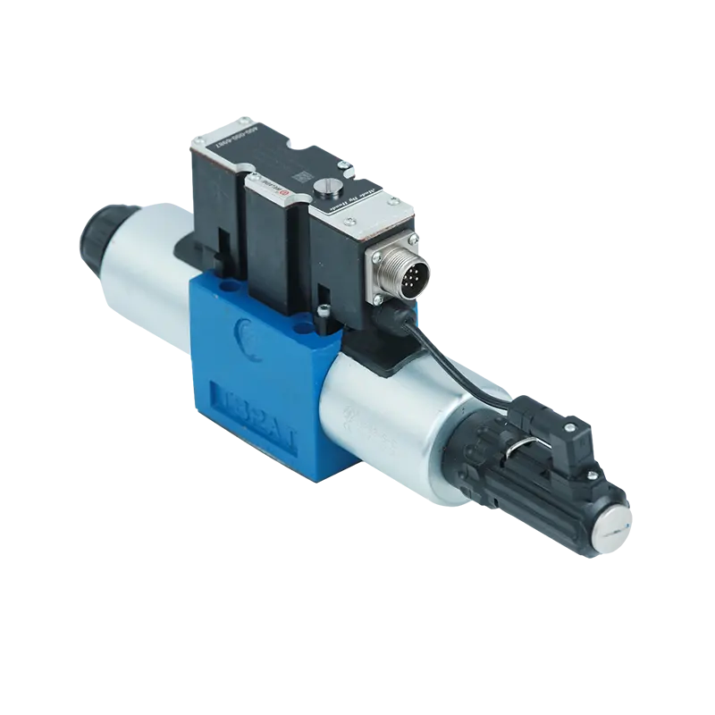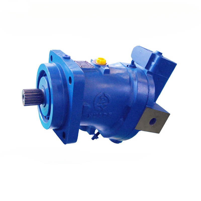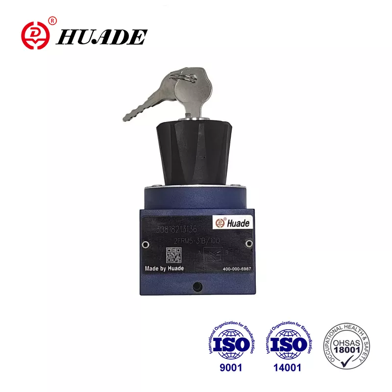
In this guide, we'll break down everything you need to know about these essential parts, from how they work to why they're so important in modern machinery.
What is a Hydraulic Flow Control Valve?
Think of a hydraulic flow control valve like a smart water faucet. Just as you turn a faucet handle to control how fast water flows out, a hydraulic flow control valve controls how fast hydraulic fluid flows through a system.
But unlike your kitchen faucet, these valves are much more sophisticated. They can automatically adjust the flow to keep machines running at exactly the right speed, even when conditions change.
Key Purpose: Control the speed of hydraulic cylinders and motors by regulating fluid flow.
How Does It Work? The Basic Principle
The Simple Explanation
Imagine you're drinking a thick milkshake through a straw. If you want to drink slower, you might pinch the straw to make it narrower. That's exactly how a basic hydraulic flow control valve works – it creates a narrow opening (called an orifice) that limits how much fluid can pass through.
The Technical Side Made Simple
The valve works on a principle called "throttling." Here's what happens:
- Fluid enters the valve at high pressure
- The valve creates a restriction (like pinching that straw)
- Pressure drops as fluid passes through the narrow opening
- Flow rate decreases, slowing down the connected equipment
The relationship follows a simple rule: the smaller the opening, the slower the flow.
Types of Hydraulic Flow Control Valves
1. Simple Throttling Valves (The Basic Models)
These are like manual volume controls on old radios. You set them once, and they stay at that setting.
Examples:
- Needle valves: Have a pointed needle that moves in and out of a small hole
- Ball valves: Use a ball with a hole through it to control flow
- Orifice plates: Have a fixed-size hole that never changes
Pros:
- Cheap and simple
- Easy to understand and maintain
Cons:
- Flow changes when the load changes
- Not very precise
2. Pressure-Compensated Valves (The Smart Ones)
These are like cruise control for your car – they automatically adjust to maintain consistent performance.
How they work:
- They have a special component called a "compensator spool"
- This spool senses pressure changes and adjusts automatically
- Result: steady flow even when loads change
Example: If a hydraulic cylinder suddenly has to lift a heavier weight, a regular valve would slow down. But a pressure-compensated valve automatically opens more to maintain the same speed.
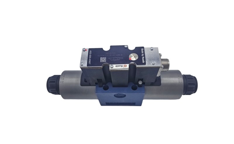
3. Proportional and Servo Valves (The High-Tech Champions)
These are like smartphone controls – they respond to electronic signals and can be programmed for exact performance.
Features:
- Controlled by electrical signals
- Can change flow rates in milliseconds
- Extremely precise (within 3-5% accuracy)
Where you'll find them:
Flow Control Methods: Three Ways to Control Speed
Method 1: Meter-In Control
What it does: Controls flow going INTO the hydraulic cylinder
Best for: When you need precise control for normal loads
Think of it like: Controlling how fast you fill a bucket
Method 2: Meter-Out Control
What it does: Controls flow coming OUT of the hydraulic cylinder
Best for: Heavy loads that might "run away" (like lowering a heavy weight)
Think of it like: Controlling how fast you empty a bucket
Method 3: Bypass Control
What it does: Sends extra fluid back to the tank instead of to the cylinder
Best for: Energy-efficient systems
Think of it like: Having an overflow drain that prevents overfilling
Real-World Applications: Where You'll Find These Valves
Construction Equipment
- Excavators: Control digging speed and precision
- Cranes: Ensure smooth, safe lifting and lowering
- Bulldozers: Manage blade movement for accurate grading
Manufacturing
- CNC machines: Precise tool positioning for perfect cuts
- Injection molding: Control plastic flow for consistent products
- Assembly lines: Synchronize multiple moving parts
Transportation
- Aircraft: Landing gear operation and flight controls
- Ships: Steering systems and cargo handling
- Trains: Brake systems and door operations
Everyday Items
Common Problems and Solutions
Symptoms:
Machine moves fast sometimes, slow other times
Causes:
- Dirty hydraulic fluid
- Worn valve parts
- Wrong valve type for the job
Solutions:
- Change hydraulic fluid and filters
- Replace worn seals and parts
- Upgrade to pressure-compensated valve
Symptoms:
Fluid gets too hot, system shuts down
Causes:
- Valve creating too much restriction
- Poor fluid circulation
Solutions:
- Check valve settings
- Improve cooling system
- Use larger valve if needed
Symptoms:
Equipment starts and stops roughly
Causes:
- Valve opening/closing too quickly
- Air in the system
- Wrong viscosity fluid
Solutions:
- Adjust valve response time
- Bleed air from system
- Use correct fluid type
Maintenance Tips: Keep Your Valves Happy
- Monitor system temperature
- Listen for unusual noises
- Check for fluid leaks
- Check fluid levels
- Inspect connections
- Clean external surfaces
- Test valve response
- Check filter condition
- Review system pressure logs
- Replace hydraulic fluid
- Rebuild or replace worn valves
- Professional system inspection
Choosing the Right Valve: A Buyer's Guide
Consider Your Needs
For Simple Applications:
- Basic throttling valves
- Lower cost
- Easy maintenance
For Variable Loads:
- Pressure-compensated valves
- More reliable performance
- Higher initial cost but better long-term value
For Precision Work:
- Proportional or servo valves
- Highest accuracy
- Most expensive but worth it for critical applications
Key Specifications to Check
Match to your pump capacity
Must handle your system pressure plus safety margin
Consider your operating environment
How quickly it reacts to changes
How precise the control needs to be
The Future of Hydraulic Flow Control
Smart Valves Are Coming
Modern valves are getting "smart" with features like:
Energy Efficiency Focus
New designs are focusing on:
Market Growth
The hydraulic valve market is booming, expected to reach $73.8 billion by 2032. This growth is driven by:
- Infrastructure development
- Factory automation
- Renewable energy projects
Key Takeaways
- Hydraulic flow control valves are like smart faucets that regulate fluid flow to control machine speed
- Three main types exist: simple throttling, pressure-compensated, and electronic valves
- They're everywhere: from construction sites to your car's brakes
- Proper maintenance is crucial for reliable operation
- Choose the right type based on your specific needs and budget
- The future is smart and efficient with connected, self-monitoring valves
Conclusion
Hydraulic flow control valves might seem like small, simple components, but they're the unsung heroes of modern machinery. They make possible the precise, reliable operation of everything from giant construction equipment to delicate surgical robots.
Understanding how these valves work helps you appreciate the engineering marvels around us and make better decisions when selecting, maintaining, or troubleshooting hydraulic systems.
Whether you're a student learning about hydraulics, a technician working on equipment, or someone simply curious about how things work, hydraulic flow control valves represent a perfect example of how simple principles can create complex, useful solutions.
The next time you see a smooth-operating excavator or a precisely controlled factory machine, you'll know there's a hydraulic flow control valve working behind the scenes, quietly ensuring everything runs just right.


