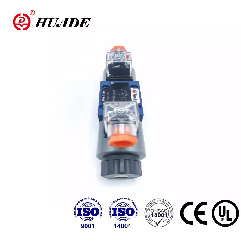
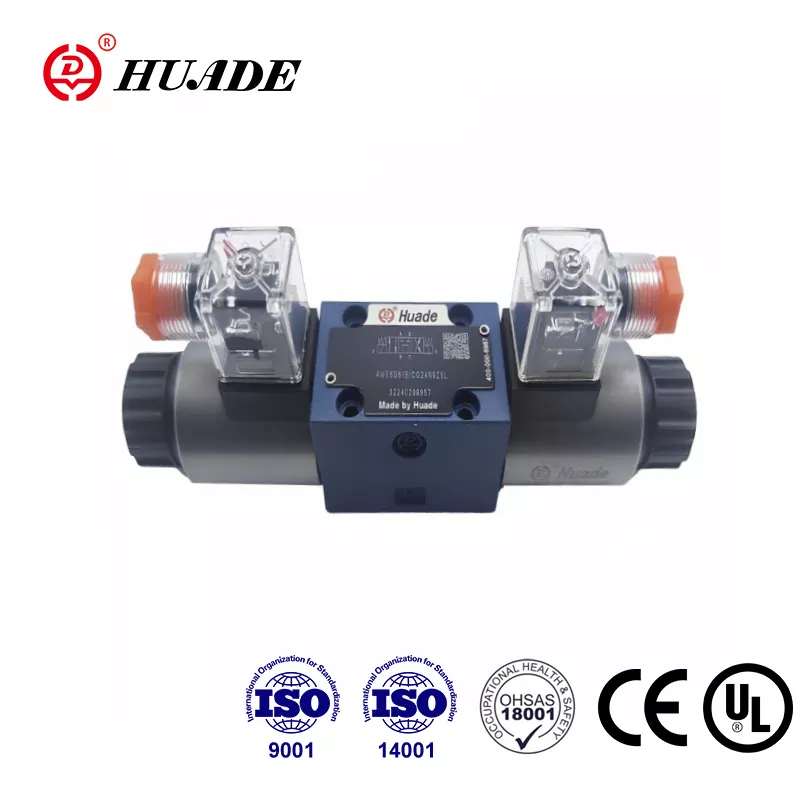
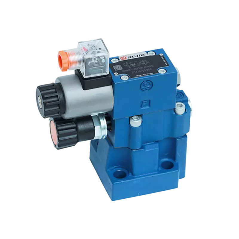
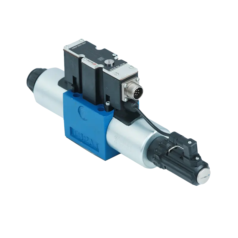
When you're working with hydraulic systems in factories or on construction equipment, one component shows up again and again: the directional control valve. The Rexroth 4WE 6 E is one of the most widely used valves in industrial hydraulics, and for good reason. This valve controls how hydraulic fluid moves through a system, which means it controls how machines move and operate.
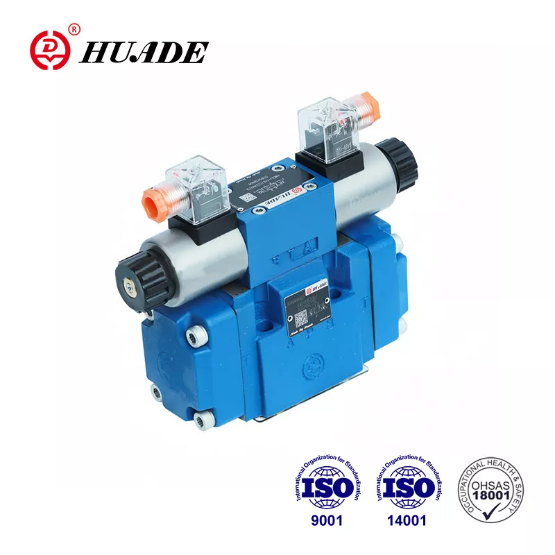
The 4WE 6 E is what engineers call a solenoid-operated directional spool valve. That sounds complicated, but the basic idea is simple. When electricity flows to the valve's solenoid (an electromagnetic coil), it pushes a metal spool inside the valve body. This spool movement redirects hydraulic fluid from one port to another, changing the direction that a hydraulic cylinder or motor moves. When the electricity stops, a spring pushes the spool back to its original position.
What Makes the 4WE 6 E Different
The "E" in the model name tells you something important about this valve's design. It means the valve uses a wet-pin solenoid, where the electromagnetic coil sits in contact with the hydraulic fluid. This design choice has several benefits. The oil helps cool the solenoid, reduces operating noise, and extends the component's working life. You can even rotate the solenoid 360 degrees on most versions, which makes installation easier in tight spaces.
The valve follows the NG6 standard, which is also called CETOP 3 or D03 in different parts of the world. This standardization matters more than you might think. It means the valve fits on standard mounting plates and can be swapped with similar valves from Parker, Vickers, or Argo Hytos without changing your hydraulic manifold. For maintenance teams, this interchangeability reduces downtime when you need a replacement part quickly.
Rexroth rates the 4WE 6 E for pressures up to 350 bar, which equals about 5,076 PSI. The maximum flow capacity reaches 80 liters per minute on DC-powered versions, or around 21 gallons per minute. These numbers put the valve in the high-performance category for its size. You'll find it controlling everything from injection molding machines to the hydraulic systems on excavators and mining equipment.
How the Valve Actually Works
Inside the valve body, the spool moves back and forth to connect different ports. The valve has four main ports that engineers label P, T, A, and B. Port P connects to your hydraulic pump, which supplies pressurized fluid. Port T connects to the reservoir or tank where fluid returns. Ports A and B connect to your hydraulic actuator, like the two sides of a cylinder.
When you energize one solenoid, the spool shifts to connect P to A and B to T. This sends pressurized fluid to one side of your cylinder while draining the other side back to the tank. Energize the other solenoid, and the connections reverse. Now P connects to B and A connects to T, moving your cylinder in the opposite direction. In the center position with no solenoids energized, the spring-centered versions hold the spool in a neutral position that blocks all ports.
The valve comes in different spool configurations that engineers call "symbols." Symbol E is common for three-position valves with spring centering. When the valve sits in its center position, all ports are blocked. Symbol HA represents a two-position valve with spring return, used when you only need motion in one direction. Some applications use detent versions marked "OF," where a mechanical pin locks the spool in place once it moves. These detent valves only need a brief electrical pulse to switch positions, which saves energy in systems that hold position for long periods.
Pressure Considerations and System Design
One number demands attention when you design systems using the 4WE 6 E: the maximum tank port pressure. While ports P, A, and B can handle 350 bar, port T typically maxes out at 160 bar, though some variants go up to 210 bar. This difference creates an important design constraint. When you run the valve at maximum working pressure with certain spool symbols, Rexroth warns that port T should be used as a drain line, not as a return line that might see back pressure from your tank or other components.
This pressure limitation connects to how spool valves work internally. The tight clearances between the spool and valve body that allow the valve to function also create internal leakage. This isn't a defect; it's an inherent characteristic of spool valve design. As the valve wears over time, this internal leakage increases gradually. The leaking fluid has to go somewhere, which is why the tank port pressure limit matters for long-term reliability.
Another pressure-related concern comes up with differential cylinders, where the rod-side area is smaller than the piston-side area. If your valve symbol blocks the rod-side return during certain switching conditions, the area ratio can intensify pressure in the rod chamber beyond the valve's 350 bar rating. This phenomenon is called pressure intensification, and it can damage cylinders or even cause dangerous failures. The solution involves adding external relief valves on the rod side of differential cylinders or choosing spool symbols that don't create this blocking condition.
Electrical Specifications and Control Options
The 4WE 6 E works with both DC and AC electrical supplies. Common DC voltages include 12, 24, 96, and 205 volts. AC versions typically run on 110/120 or 230 volts at 50 or 60 Hz. The electrical connector follows the EN 175301-803 standard with a three-pole design that includes two power connections and a ground. Most versions include built-in suppression diodes to protect against voltage spikes when the solenoid switches off.
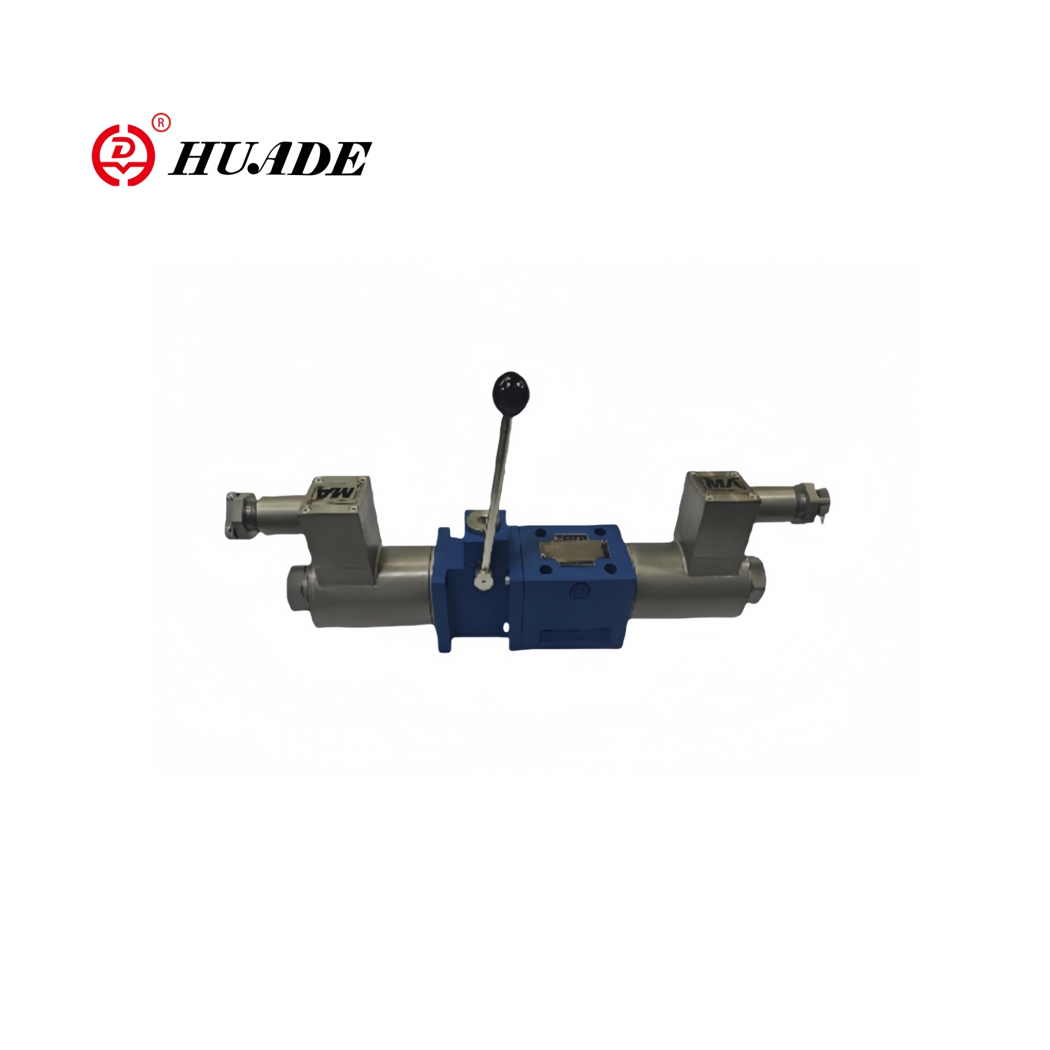
For applications in hazardous areas, Rexroth offers explosion-proof versions marked XE or VE1. These variants meet ATEX standards for European installations or NEC 505/Class I Zone 1 requirements for North American sites. The explosion-proof housings and intrinsically safe solenoids allow the valve to operate safely in environments with flammable gases or vapors, like chemical plants or offshore oil platforms.
The detent option with "OF" designation provides significant advantages for energy efficiency. Instead of keeping a solenoid energized continuously to hold position, you send a 100-millisecond pulse to shift the spool, then the mechanical detent locks it in place. This reduces heat generation, extends solenoid life, and cuts electrical consumption. Machine tool builders use this feature for hydraulic clamping systems that must hold workpieces firmly during long machining operations.
Fluid Compatibility and Seal Materials
The standard 4WE 6 E comes with NBR (nitrile rubber) seals that work with most mineral-based hydraulic oils meeting HLP or HVLP specifications. NBR seals also handle water-glycol fire-resistant fluids in the HFC category. However, if your system uses biodegradable hydraulic fluids like HETG, HEES, or HEPG, or synthetic fire-resistant fluids like HFDU or HFDR, you must specify FKM (fluorocarbon) seals when ordering.
Getting the seal material wrong causes rapid deterioration and system failure. If you're replacing seals during maintenance, check what fluid your system actually uses before ordering parts. The NBR seal kit carries part number 3492432, while the FKM kit is 3120269. Using the wrong kit means you'll be tearing the valve apart again in a few months after the incompatible seals swell, crack, or disintegrate.
Rexroth specifies that hydraulic fluid must meet ISO 4406 Class 20/18/15 cleanliness standards. This three-number code indicates the maximum particle counts at different size ranges. Cleaner fluid reduces wear on the precision-machined spool and bore surfaces. Contaminated fluid accelerates wear, increases internal leakage, and can cause the spool to stick or move erratically. Installing proper filtration with elements rated at 10 micrometers or finer protects your valve investment and extends service life.
Installation and First Operation
The valve mounts directly to a standard NG6 or CETOP 3 subplate using four bolts. The mounting pattern and port locations follow ISO 4401-03-02-0-05, ensuring compatibility across manufacturers. O-rings seal each port connection, and you should apply a thin film of hydraulic fluid to these O-rings during installation to prevent pinching or rolling.
Because the solenoids use wet-pin design, the internal cavities must fill with hydraulic fluid for proper operation. During initial startup, you may need to cycle the valve several times while running the hydraulic pump to purge air from the solenoid chambers. Air trapped in these spaces affects solenoid force and valve response time. Some installations include small vent screws on the solenoid housings to help release trapped air during commissioning.
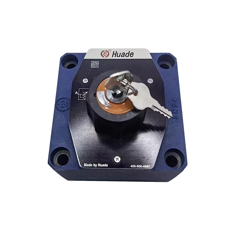
Every 4WE 6 E includes a manual override that lets you shift the valve without electrical power. The standard hidden version requires a special tool to access. Optional versions include knurled knobs or lockable mushroom-head buttons that allow manual operation during maintenance or emergency situations. On two-solenoid valves, never press both manual overrides simultaneously, as this creates a mechanical conflict that can damage internal components.
Flow Control and Soft Switching
Some versions of the 4WE 6 E come with throttle inserts, which are basically calibrated orifices installed in specific ports. The designation "/B12" indicates a 1.2-millimeter orifice at port P. These throttles don't just limit maximum flow. Their main purpose is managing the pressure spikes and flow surges that happen during rapid valve switching. By controlling the rate at which flow can change, throttle inserts reduce system shock, protect downstream components, and extend overall system life.
Certain model variants designated ".73…A12" incorporate soft switching through modified spool geometry. These versions provide roughly 85 percent shock reduction compared to standard switching. The softer transition helps in applications where valve shifting creates objectionable noise or where hydraulic shock damages piping connections and manifolds over time. The trade-off is slightly slower response, which matters in high-speed applications but offers clear benefits in systems that prioritize smooth operation and longevity.
Common Applications and Use Cases
The 4WE 6 E directional control valve appears throughout industrial automation. Injection molding machines use these valves to control mold clamping forces and ejector movements. The valve's high pressure rating and reliable switching make it suitable for the demanding duty cycles in plastics processing. Rubber molding equipment uses similar valve configurations for press control and part ejection.
Construction and mobile equipment incorporate the 4WE 6 E in excavator arm circuits, bulldozer blade controls, and crane boom functions. The valve's compact size relative to its flow capacity saves space in crowded mobile hydraulic systems. Its standardized mounting allows equipment manufacturers to source from multiple suppliers without redesigning manifolds.
Machine tool builders install these valves in grinding machines, milling centers, and automated production lines. The detent versions work particularly well in fixtures and clamping systems that must hold position reliably without consuming electrical power continuously. Unattended machining operations benefit from the energy savings and reduced heat generation of pulse-operated detent valves.
Troubleshooting and Maintenance
When a 4WE 6 E doesn't operate correctly, several common issues usually explain the problem. Slow or inconsistent shifting often points to contaminated fluid allowing the spool to stick in its bore. Checking the system filter differential pressure indicator tells you if filtration is keeping up with contamination generation. If filters are overdue for replacement, that's your first fix.
Electrical problems show up as complete failure to shift or as weak, hesitant valve action. Check supply voltage at the valve connector while the solenoid should be energized. Low voltage reduces solenoid force and slows response. Loose connector pins create intermittent operation that's frustrating to diagnose. The suppression diodes built into most valves can fail shorted or open, affecting solenoid behavior.
Increasing internal leakage over the valve's service life eventually requires seal replacement or valve exchange. If you notice that a hydraulic cylinder creeps downward under load when the valve should be holding position, internal leakage is the likely cause. Installing an external load-holding valve might be a simpler fix than valve replacement if the leakage isn't severe. For critical position-holding applications, external check valves or pilot-operated check valves provide positive load holding regardless of directional valve condition.
The wet-pin solenoid design offers a maintenance advantage: you can replace the coil without draining the system or losing hydraulic fluid. Simply disconnect the electrical connector, unscrew the solenoid assembly, and swap the coil. This field-serviceability reduces downtime during repairs. When ordering replacement coils, verify both the voltage rating and the connector type match your installation.
Sizing and Selection Considerations
Choosing the right directional control valve involves matching several parameters to your application requirements. Start with pressure: if your system operates above 350 bar, the 4WE 6 E won't work. Flow capacity needs checking against your actuator speed requirements. An 80 liter per minute valve might seem adequate on paper, but if you're running near that limit, pressure drop across the valve increases and heat generation becomes a problem.
Think about duty cycle and switching frequency. Applications that switch continuously benefit from AC solenoids, which handle heat better due to higher thermal mass. DC solenoids work well for intermittent duty and offer faster response times. If your system needs to hold position for extended periods without motion, specify detent configuration to eliminate continuous solenoid energization.
The spool symbol determines valve function in center position and at each extreme position. Study the hydraulic schematic symbols carefully to understand what each port connection configuration does to your actuator. Symbol E (all ports blocked in center) suits applications where you want stopped actuators to resist external forces. Symbol P-to-T in center provides free circulation that reduces heat generation during idle periods. Choose the symbol that matches your functional requirements.
Competitive Alternatives and Cross-References
While the Rexroth 4WE 6 E is a leading product, several other manufacturers produce functionally equivalent valves. Parker's D1VW009CNT series offers direct replacement capability with similar pressure and flow ratings. Vickers, now part of Eaton, manufactures the DG4V-3-8C series that swaps directly onto NG6 subplates. Argo Hytos provides the RPE3-063C11 as another interchangeable option.
This cross-manufacturer compatibility gives procurement departments flexibility. If your primary supplier faces long lead times or stock shortages, alternatives exist without redesigning your hydraulic system. Price competition among these manufacturers benefits buyers, though Rexroth's extensive distribution network and technical support often justify any price premium.
When substituting valves from different manufacturers, verify that spool symbols match functionally, not just nominally. What one manufacturer calls "Symbol E" might have subtly different port connections than another manufacturer's version. Review the detailed port connection diagrams in each manufacturer's catalog before finalizing a cross-reference substitution.
Pricing and Procurement Strategy
Market pricing for the 4WE 6 E varies by region, configuration, and purchase volume. In North America, expect prices around $140 for standard configurations purchased individually. Indian markets show pricing between ₹7,799 and ₹9,203, while Malaysian distributors list around RM196.50. These variations reflect local distribution costs, import duties, and market competition.
Minimum order quantities from most distributors start at one piece, making small purchases practical. Lead times typically run seven to ten days for standard configurations, though common voltage and symbol combinations often ship from distributor stock. Less common configurations might extend to several weeks if they require factory build-to-order.
For maintenance departments managing critical spares inventory, consider stocking one or two commonly used configurations as insurance against unexpected failures. The valve's long service life means spares might sit on shelves for years, but the cost of stocking a spare is minimal compared to equipment downtime costs. Make sure your stock includes any special configurations like FKM seals if your system uses non-standard fluids.
Final Recommendations
The Rexroth 4WE 6 E directional control valve delivers reliable performance in a compact, industry-standard package. Its 350 bar pressure rating and 80 liter per minute flow capacity provide strong capability in the NG6 size class. The wet-pin solenoid design balances performance with serviceability, and the standardized mounting ensures broad compatibility across hydraulic systems.
When specifying or maintaining these valves, pay attention to the details that matter most. Match seal materials to your hydraulic fluid chemistry. Size the valve conservatively to avoid excessive pressure drop and heat generation. Consider detent versions for energy savings in position-holding applications. Protect differential cylinders from pressure intensification through proper circuit design.
Understanding how the valve works, what its limitations are, and how it fits into the competitive landscape helps you make better decisions about selection, maintenance, and troubleshooting. The 4WE 6 E isn't perfect for every application, but within its design envelope, it provides proven performance that explains its widespread adoption across industrial hydraulics.
