When a hydraulic cylinder suddenly encounters increased resistance—like an excavator bucket hitting bedrock—a standard throttle valve would cause the cylinder to slow down noticeably. This happens because flow rate through an orifice depends on both the opening area and the pressure differential across it, following Bernoulli’s principle:
$$ Q = C_d cdot A cdot sqrt{frac{2Delta P}{rho}} $$
A pressure compensated flow control valve solves this fundamental problem by automatically adjusting its internal resistance to maintain constant flow regardless of load pressure fluctuations. Let’s examine exactly how this mechanical feedback system achieves load-independent speed control.
The Core Operating Principle: Differential Pressure Regulation

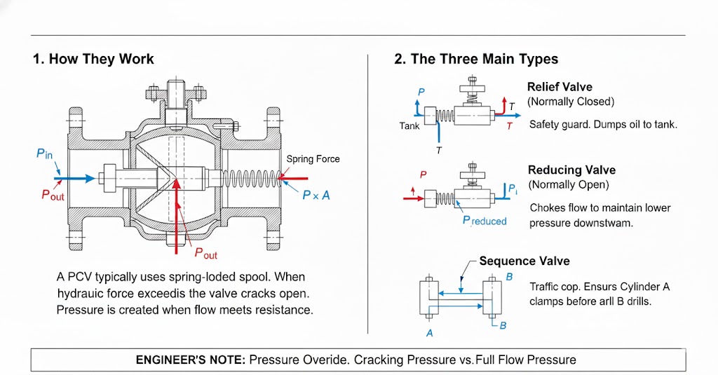
A pressure compensated flow control valve consists of two essential components working in series: a user-adjustable throttle orifice and an automatic pressure compensator (hydrostat). The compensator spool experiences three primary forces:
$$ P_{inlet} cdot A_{spool} = P_{load} cdot A_{spool} + F_{spring} $$
This simplifies to:
$$ P_{inlet} – P_{load} = frac{F_{spring}}{A_{spool}} = Delta P_{constant} $$
The compensator doesn’t control its own pressure drop—it controls the pressure drop across the main throttle orifice. By sensing pressures before and after the user-set orifice, it automatically adjusts to keep $Delta P$ constant (typically 0.5-1.5 MPa). Since flow depends on $sqrt{Delta P}$, maintaining constant $Delta P$ makes flow dependent only on orifice area.
Step-by-Step Response to Load Changes
- Initial State: Valve delivers 20 L/min. Compensator maintains 70 bar drop across main orifice.
- Load Increases: Load jumps to 80 bar. Main orifice $Delta P$ momentarily drops to 40 bar.
- Compensator Reacts: Force imbalance pushes the spool open wider.
- New Equilibrium: Inlet pressure rises until main orifice inlet hits 150 bar (150 – 80 = 70 bar restored). Total reaction time: 50-200 ms.
Pre-Compensation vs Post-Compensation Architectures

The position of the compensator relative to the throttle orifice creates two distinct system behaviors.
Pre-Compensation (Traditional Load Sensing)
The compensator sits upstream. In multi-actuator systems, if flow demand exceeds supply (saturation), the path of least resistance steals flow while heavy loads starve. This causes dangerous, unpredictable machine behavior.
Post-Compensation (LUDV Flow Sharing)
Compensators sit downstream and reference the highest load pressure in the entire circuit. When saturation occurs, all orifice pressure differentials decrease simultaneously and proportionally. A boom and swing operating together both slow down by the same percentage, preserving the movement trajectory.
| Feature | Pre-Compensation | Post-Compensation (LUDV) |
|---|---|---|
| Location | Upstream of throttle | Downstream of throttle |
| Control Target | Maintains individual valve $Delta P$ | Equalizes all branch outlet pressures |
| Saturation Behavior | Light loads steal flow | Proportional flow reduction |
| Typical Applications | Single-actuator circuits | Excavators, cranes, mobile equipment |
Two-Way vs Three-Way Valve Configurations
Two-Way Valves (Series Restrictor): Poor efficiency in fixed-displacement systems. Excess flow dumps over the relief valve at full pressure.
Loss = 30 L/min × 200 bar = 10 kW heat.
Three-Way Valves (Bypass Type): Adds a bypass port. Excess flow bypasses to tank at load pressure + spring pressure (e.g., 60 bar).
Loss = 30 L/min × 60 bar = 3 kW heat (70% reduction).
Dynamic Stability and Damping Design
A pressure compensator is a mass-spring-damper system. Insufficient damping leads to “hunting” (oscillation). Engineers control damping by placing a small orifice (0.3-0.8 mm) in the control line. This is a critical tradeoff: small orifices provide stability but slow response; large orifices enable speed but risk oscillation.
Steady-State Flow Forces and Temperature
Flow Forces: Fluid momentum creates a closing force on the spool, acting like a variable spring. High-performance valves use shaped lands to deflect the jet and minimize this “droop” error.
Temperature Compensation: To counter viscosity changes, valves use sharp-edged orifices (knife-edge) to create turbulent flow where $C_d$ is independent of Reynolds number. Some designs use bimetallic elements to physically adjust the orifice as temperature rises.
Common Failure Modes and Diagnostics
Understanding failure mechanisms is essential for maintenance planning.
| Symptom | Root Cause | Remedy |
|---|---|---|
| Flow varies with load | Compensator spool sticking | Clean/Replace. Improve filtration. |
| No flow output | Spool jammed fully closed | Check for pressure shock or debris. |
| Hunting (Oscillation) | Blocked damping orifice / Air | Clean passages. Bleed air. |
| External leakage | Seal deterioration | Replace seal kit (check temp limits). |
ISO Symbol Recognition
Hydraulic schematic interpretation requires recognizing these symbols:
- Two-Way: Two ports, sensing lines before/after throttle.
- Three-Way: Adds a bypass port for excess flow.
- Post-Compensated: Compensator symbol shown downstream of the throttle.