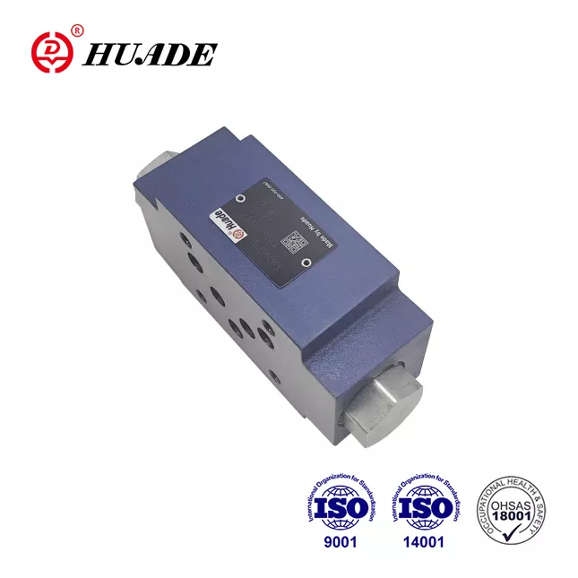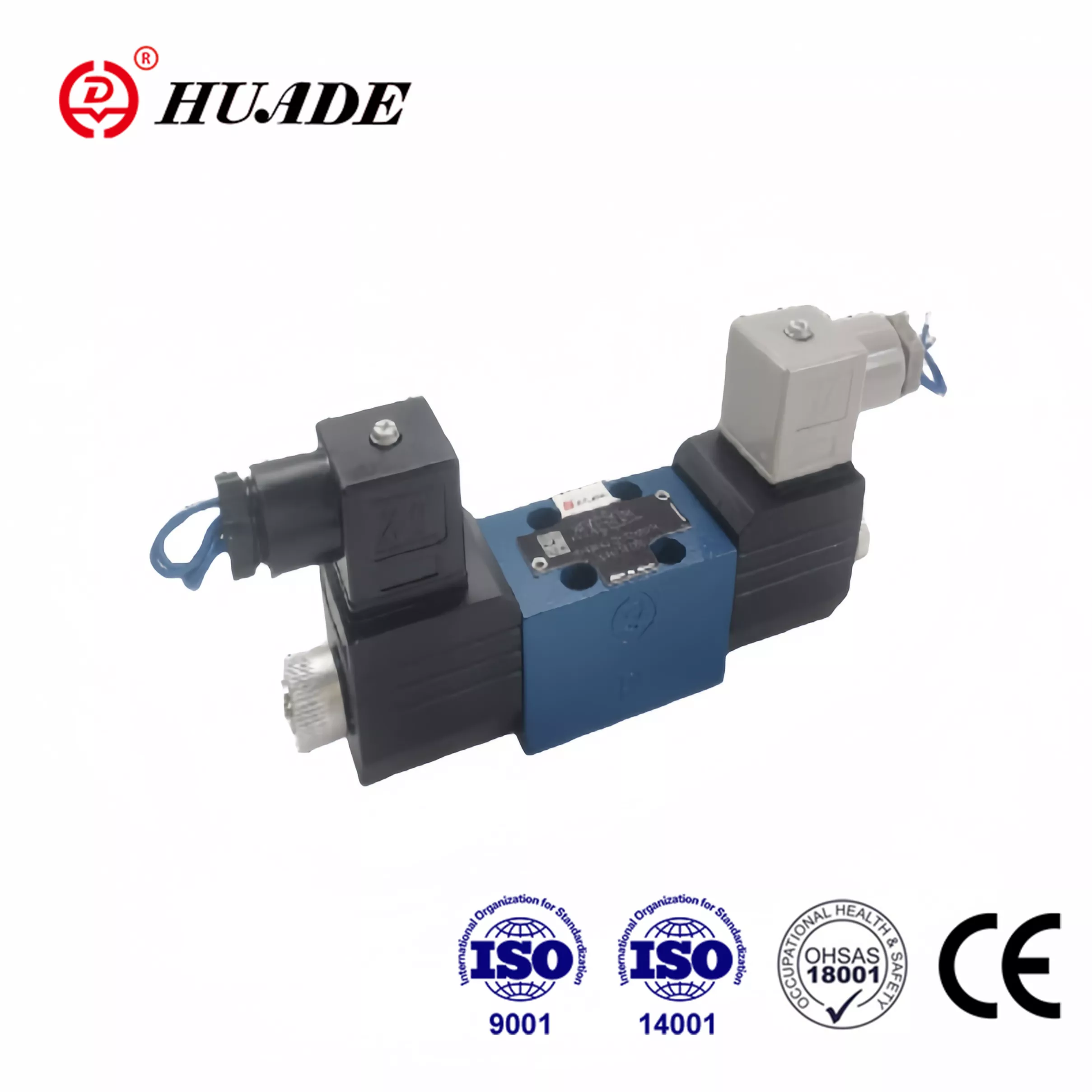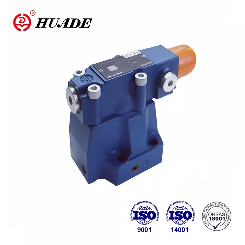
This comprehensive guide explains hydraulic proportional control technology in simple terms, covering everything from basic working principles to advanced servo control applications.
What is a Hydraulic Proportional Valve?
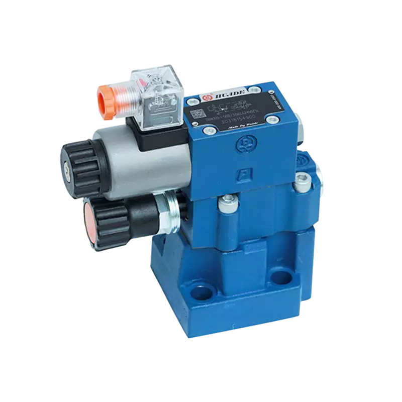
A hydraulic proportional valve is an electro-hydraulic device that converts electrical input signals into proportional hydraulic outputs. Unlike simple on/off solenoid valves, proportional valves provide continuous, variable control over fluid flow, pressure, and direction. For comprehensive overview, see what is a proportional valve.
Key characteristics:
- Converts analog electrical signals (0-10V, 4-20mA) into precise hydraulic control
- Provides infinite positioning between fully open and closed states
- Enables smooth, gradual machine movements
- Integrates seamlessly with PLC control systems and automation networks
Think of it as a dimmer switch for hydraulic power—giving you exact control instead of just "full power" or "off."
How Hydraulic Proportional Valves Work: The Control Process
Basic Operating Principle
The valve controller sends an analog electrical signal (typically 0-10V DC or 4-20mA current loop) to the proportional solenoid actuator.
The proportional solenoid converts electrical current into magnetic force. Higher current = stronger magnetic field = greater actuator force.
Magnetic force moves the valve spool against spring resistance. Spool position directly corresponds to input signal strength.
Spool movement varies the hydraulic orifice opening, controlling flow rate, pressure, or directional flow paths.
LVDT position sensors or pressure transducers provide real-time feedback to the valve amplifier for precise servo control.
Advanced Control Technologies
Pulse Width Modulation (PWM): Reduces power consumption and heat generation while maintaining precise force control.
Dither Frequency: Small oscillations (typically 100-300 Hz) overcome static friction and improve valve resolution to ±0.1% of full scale.
Signal Ramping: Gradual input changes prevent hydraulic shock and ensure smooth actuator acceleration/deceleration.
Technical Specifications and Performance Parameters
Critical Performance Metrics
| Parameter | Typical Range | High-Performance |
|---|---|---|
| Flow Capacity | 10-500 L/min | Up to 2000 L/min |
| Operating Pressure | 210-350 bar | Up to 700 bar |
| Response Time | 50-200 ms | 15-50 ms |
| Linearity | ±3-5% | ±1% |
| Hysteresis | 2-5% | <1% |
| Resolution | 0.5-1% | 0.1% |
| Frequency Response | 10-50 Hz | 100+ Hz |
Signal Compatibility
Voltage Control: ±10V, 0-10V DC
Current Control: 4-20mA, 0-20mA
Digital Protocols: CANopen, EtherCAT, IO-Link, Profinet
Feedback Types: LVDT, potentiometer, pressure transducer
Types of Proportional Control Valves
1. Proportional Flow Control Valves
Function: Regulate volumetric flow rate for speed control
Applications: CNC machine tools, robotic actuators, conveyor systems
Flow Range: 5-500 L/min with ±2% accuracy
2. Proportional Pressure Relief/Reducing Valves
Function: Maintain constant pressure or limit maximum system pressure
Applications: Injection molding, material testing, clamping systems
Pressure Range: 5-350 bar with ±1% regulation accuracy
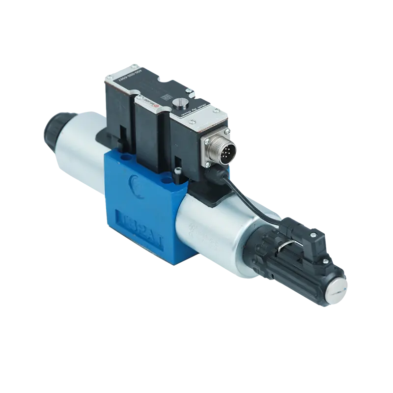
3. Proportional Directional Control Valves
Function: Control flow direction and rate simultaneously
Configurations: 4/3-way, 4/2-way with proportional flow control
Applications: Mobile hydraulics, industrial automation, servo positioning
4. Two-Stage Servo-Proportional Valves
Function: High-flow applications with servo-level precision
Pilot Stage: Small servo valve controls main stage spool
Applications: Steel rolling mills, large presses, marine steering systems
Proportional vs. Servo vs. Standard Valves: Technical Comparison
| Specification | Standard Valve | Proportional Valve | Servo Valve |
|---|---|---|---|
| Control Resolution | On/Off Only | 0.1-1% | 0.01-0.1% |
| Frequency Response | N/A | 10-50 Hz | 100-500 Hz |
| Pressure Drop | 5-20 bar | 5-15 bar | 3-10 bar |
| Contamination Tolerance | ISO 20/18/15 | ISO 19/16/13 | ISO 16/14/11 |
| Cost Factor | 1x | 3-5x | 8-15x |
| Maintenance Interval | 2000 hrs | 3000-5000 hrs | 1000-2000 hrs |
Advanced Applications and Industry Use Cases
Manufacturing Automation
- Injection Molding: Pressure control within ±0.5% for consistent part quality
- Metal Forming: Force control up to 5000 tons with proportional pressure regulation
- Assembly Lines: Speed matching between multiple actuators within ±1%
Mobile Equipment
- Excavator Control: Joystick-to-valve response time <100ms for operator comfort
- Crane Operations: Load-sensing pressure control for energy efficiency
- Agricultural Machinery: Variable displacement pump control for PTO applications
Aerospace and Defense
- Flight Simulators: Motion platform control with ±0.1mm positioning accuracy
- Aircraft Systems: Landing gear and flight control surface actuation
- Test Equipment: Fatigue testing with precise force and frequency control
Control System Integration and Networking
PLC Integration
Most proportional valves interface with programmable logic controllers through:
- Analog I/O: 4-20mA current loops or ±10V voltage signals
- Valve Amplifiers: Convert PLC outputs to proper valve drive signals
- On-Board Electronics (OBE): Integrated control electronics simplify wiring
Industrial Communication Protocols
- EtherCAT: Real-time Ethernet for high-speed servo applications
- CANopen: Distributed control in mobile and industrial equipment
- IO-Link: Point-to-point communication for smart sensor integration
- Profinet/Profibus: Siemens automation ecosystem compatibility
Closed-Loop Control Algorithms
- PID Control: Proportional-Integral-Derivative feedback control
- Feed-Forward: Anticipatory control for improved dynamic response
- Adaptive Control: Self-tuning parameters for varying load conditions
Troubleshooting and Diagnostic Procedures
Common Failure Modes and Solutions
Spool Sticking (80% of failures)
Cause: Contaminated hydraulic fluid or varnish buildup
Solution: Flush system, replace filters, maintain ISO 19/16/13 cleanliness
Prevention: 500-hour filter replacement, fluid analysis
Signal Drift/Linearity Loss
Cause: Temperature effects, component aging, electrical interference
Solution: Recalibration, EMI shielding, temperature compensation
Test Procedure: 5-point linearity check with calibrated instrumentation
Slow Response Time
Cause: Internal leakage, insufficient supply pressure, electrical issues
Solution: Seal replacement, pressure optimization, amplifier tuning
Measurement: Step response test with oscilloscope monitoring
Predictive Maintenance Strategies
- Vibration Analysis: Detect mechanical wear in valve components
- Oil Analysis: Monitor contamination levels and additive depletion
- Thermal Imaging: Identify electrical connection problems
- Performance Trending: Track response time and accuracy degradation
Selection Criteria and Sizing Guidelines
Flow Requirements
Calculate required flow:
- Q = Flow rate (L/min)
- A = Actuator area (cm²)
- V = Desired speed (m/min)
- η = System efficiency (0.85-0.95)
Size valve for 120-150% of calculated flow for optimal control.
Pressure Ratings
- System Pressure: Valve rating ≥ 1.5 × maximum system pressure
- Pressure Drop: Maintain 10-15 bar across valve for good control
- Back Pressure: Consider return line restrictions in sizing
Environmental Considerations
- Temperature Range: Standard (-20°C to +80°C), High-temp options available
- Vibration Resistance: IEC 60068-2-6 compliance for mobile applications
- IP Protection: IP65/IP67 ratings for harsh environments
- Explosion Protection: ATEX/IECEx certification for hazardous areas
Future Trends in Proportional Valve Technology
Industry 4.0 Integration
- IoT Connectivity: Wireless monitoring and cloud-based analytics
- Machine Learning: Predictive algorithms for optimal performance
- Digital Twin: Virtual valve models for system simulation
- Blockchain: Secure maintenance records and parts authentication
Advanced Materials and Design
- Additive Manufacturing: Complex internal geometries for improved flow characteristics
- Smart Materials: Shape-memory alloys for adaptive control
- Nanotechnology: Advanced coatings for improved wear resistance
- Bio-Inspired Design: Fluid dynamics optimization from nature
Sustainability Focus
- Energy Recovery: Regenerative circuits with proportional control
- Biodegradable Fluids: Compatibility with environmentally friendly hydraulics
- Lifecycle Assessment: Design for recyclability and reduced environmental impact
- Efficiency Optimization: AI-driven control for minimum energy consumption
Cost-Benefit Analysis and ROI Considerations
Initial Investment vs. Operating Savings
Typical Payback Calculation:
Proportional valve premium: $2,000-5,000
Energy savings: 15-30% of hydraulic power consumption
Reduced maintenance: 25% fewer service calls
Improved productivity: 10-15% cycle time reduction
Average ROI: 12-24 months in high-utilization applications
Total Cost of Ownership Factors
- Energy Consumption: Variable vs. fixed flow systems
- Maintenance Costs: Scheduled vs. reactive maintenance strategies
- Downtime Reduction: Predictive maintenance capabilities
- Product Quality: Improved consistency reduces scrap rates
Conclusion
Hydraulic proportional valves represent a critical technology bridging traditional hydraulic power with modern electronic control systems. Their ability to provide precise, continuous control makes them essential for applications demanding accuracy, efficiency, and smooth operation.
Key takeaways for implementation:
- Match valve specifications to application requirements carefully
- Invest in proper system design and fluid cleanliness
- Plan for integration with existing control architectures
- Consider long-term maintenance and support requirements
As manufacturing moves toward greater automation and precision, proportional valve technology continues evolving with smarter diagnostics, better connectivity, and enhanced performance capabilities.
Whether upgrading existing equipment or designing new systems, understanding proportional valve technology helps optimize hydraulic system performance while preparing for future Industry 4.0 integration requirements.
Ready to implement proportional valve technology in your hydraulic systems? Consider consulting with experienced automation engineers to ensure optimal selection and integration for your specific applications.


