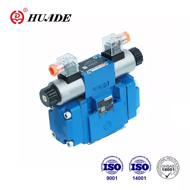
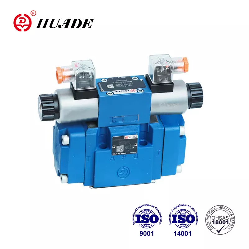
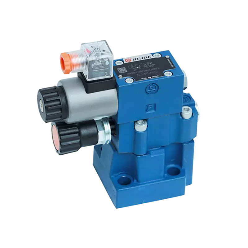
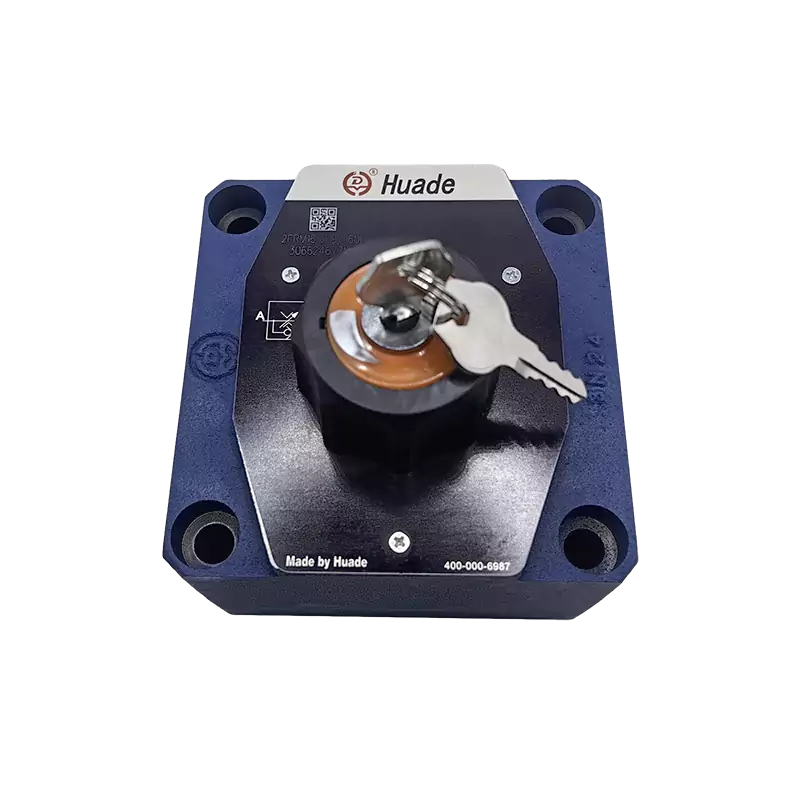
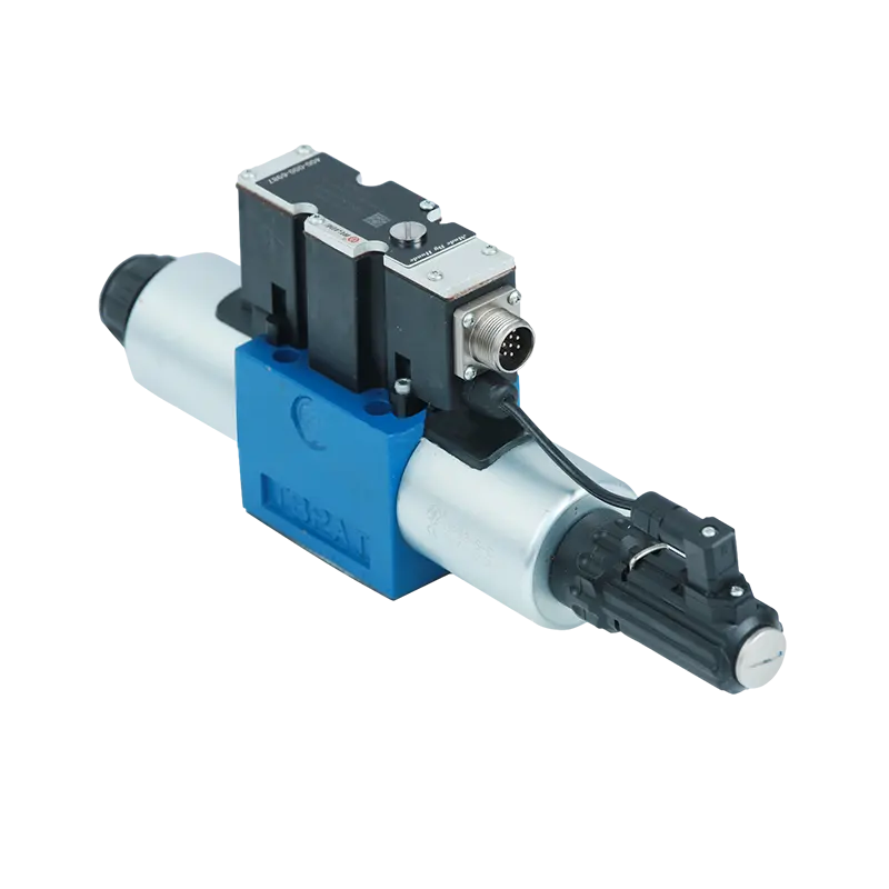
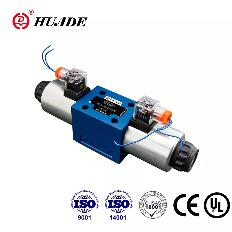
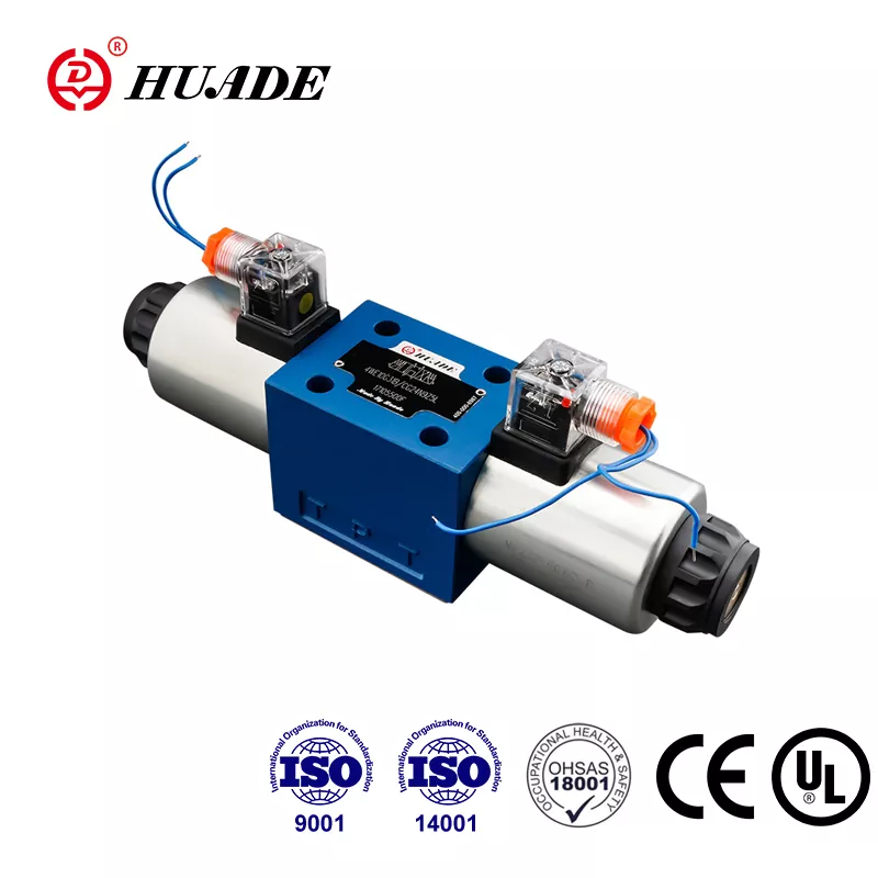
When you're working with heavy-duty hydraulic systems, choosing the right directional control valve can make or break your operation. The Bosch Rexroth 4WEH 16 J is one of those components that experienced engineers trust for demanding industrial applications. This valve has earned its reputation through reliable performance in injection molding machines, metal forming presses, and construction equipment where failure simply isn't an option.
The 4WEH 16 J represents a specific configuration within Bosch Rexroth's WEH series of electro-hydraulic pilot-operated directional control valves. The designation tells you quite a bit if you know how to read it. The "16" indicates the nominal size (NG16), which corresponds to CETOP 7 mounting standards. The "J" describes the spool function, specifically a 4-way, 3-position closed center design. Understanding what these specifications mean in practical terms will help you determine whether this valve suits your application.
What Makes the 4WEH 16 J Different
The directional control valve 4WEH 16 J operates using a two-stage pilot system. Instead of directly moving the main spool with electromagnets, this valve uses small pilot valves to control hydraulic pressure that shifts the larger main spool. This approach requires less electrical power while controlling substantial hydraulic flows. The standard version runs on 24 VDC power, making it compatible with most industrial control systems without requiring special electrical infrastructure.
The valve can handle pressures up to 350 bar in its H-version configuration, which translates to about 5,076 psi. For flow capacity, the nominal maximum sits at 300 liters per minute, though actual performance depends on pressure drop across the valve. These specifications place the 4WEH 16 J in the category of heavy-duty industrial valves rather than mobile equipment or light-duty applications.
Weight matters when you're planning installations and maintenance procedures. At 9.84 kilograms (about 21.7 pounds), the valve isn't something you'll casually move around, but it's manageable with proper handling. The substantial construction contributes to durability in harsh industrial environments where vibration, temperature swings, and contamination are daily concerns.
The Closed Center Design and System Compatibility
The "J" spool configuration defines how the directional control valve 4WEH 16 J behaves in its neutral position. When the valve sits in the center position with no electrical signal applied, all four ports—P (pressure), A and B (work ports), and T (tank)—are blocked. This closed center arrangement serves a specific purpose in modern hydraulic systems.
Closed center valves work exceptionally well with pressure-compensated variable displacement pumps. When the valve blocks all ports in neutral, system pressure builds until it signals the pump to reduce flow to nearly zero. This prevents the pump from constantly churning fluid through a relief valve, which would waste energy and generate excessive heat. In an era where energy costs matter and environmental regulations tighten, this efficiency advantage becomes significant.
The trade-off involves system design complexity. Closed center systems require careful attention to pressure spikes during valve switching. When the directional control valve 4WEH 16 J shifts from blocked center to an operating position, the sudden opening can create pressure transients. Engineers typically address this through throttling inserts (identified by "B" codes in the ordering system) or by adding external shock-relief valves that respond faster than the main system relief.
How Two-Stage Operation Actually Works
The pilot-operated design of the 4WEH 16 J involves two distinct stages of control. The first stage consists of a small WE6-type pilot valve controlled by wet-pin solenoids. When you energize a solenoid, it shifts the pilot valve, directing pilot pressure from the X port into control chambers at the ends of the main spool. This pilot pressure overcomes the centering springs and moves the main spool to connect the appropriate flow paths.
The second stage is the main spool movement itself. As pilot pressure builds in the control chamber, it pushes against the spool area, generating enough force to shift the spool against the centering springs and any pressure forces acting on the spool. The main spool then opens the connections between ports—either P to A with B to T, or P to B with A to T, depending on which solenoid you energized.
This two-stage arrangement requires pilot pressure between 5 and 12 bar to function properly. The pilot supply typically comes from the main system pressure through internal passages, though you can specify external pilot supply for certain applications. The switching time runs about 100 milliseconds, which is slower than direct-acting valves but acceptable for most industrial machinery where cycle times measure in seconds rather than milliseconds.
Electrical Requirements and Control Options
Standard directional control valve 4WEH 16 J configurations use 24 VDC solenoids, designated as G24 in the ordering code. The wet-pin solenoid design means the coil sits in direct contact with hydraulic fluid, which helps with cooling but requires the coil to be sealed against the fluid. These solenoids typically draw around 1.5 to 2 amps when energized, representing a modest electrical load that most PLCs and control systems handle easily.
The valve offers optional manual override capability, coded as N9 in position 11 of the ordering system. This hidden-type manual actuator lets technicians shift the valve by hand during commissioning, troubleshooting, or emergency situations. You won't accidentally bump it during normal operation, but it's accessible when you need it. This feature proves valuable when you're setting up new systems or diagnosing problems without running the electrical controls.
Electrical connections follow DIN EN 175301-803 standards in the K4 configuration, using separate connectors for each solenoid. This arrangement provides flexibility in wiring and simplifies troubleshooting since you can disconnect individual solenoids without affecting others. Some applications might specify alternate connector styles depending on the control cabinet setup and environmental protection requirements.
Pressure Ratings and Performance Boundaries
The maximum operating pressure for ports P, A, and B reaches 350 bar when you order the H-version. Standard versions are rated to 280 bar, which still covers most industrial applications. The tank port (T) typically operates at lower pressures, often just a few bar above atmospheric unless you're dealing with back pressure from long return lines or elevated tank locations.
These pressure ratings represent continuous operating limits, not momentary spikes. When the directional control valve 4WEH 16 J switches positions, pressure transients can exceed steady-state values by 50% or more for brief periods. Proper system design includes relief valves set 10-15% above maximum operating pressure to catch these transients before they damage components. The valve itself can withstand occasional pressure spikes that exceed the rated values, but sustained operation above ratings will shorten service life.
Flow capacity interacts with pressure in ways that matter for real applications. The 300 l/min nominal rating assumes specific pressure drop values across the valve. If you're running at lower flow rates, pressure drop decreases. Push toward maximum flow, and pressure drop increases, which means your pump needs to generate higher pressure to overcome both the valve resistance and the load. Manufacturer flow curves show these relationships, and you should consult them when sizing pumps and estimating system efficiency.
Mounting and Installation Considerations
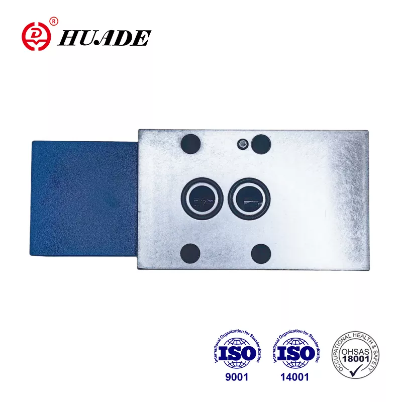
The directional control valve 4WEH 16 J follows ISO 4401-07-07-0-05 standards, which ensures compatibility with CETOP 7 mounting surfaces. This standardization means you can potentially substitute valves from different manufacturers without redesigning the mounting manifold, though you should verify all specifications match before attempting substitutions. The mounting bolt pattern, port locations, and overall envelope dimensions follow industry standards that have been around for decades.
Installation requires attention to several factors beyond just bolting the valve to a manifold. Pilot supply configuration, indicated by position 12 in the ordering code, determines how pilot and drain oil flow through the system. The default configuration uses external pilot supply and external drain, which isolates the valve's internal passages from back pressure in the tank line. This setup works best for applications where the tank line might see elevated pressure from other components.
Alternative configurations include internal pilot supply with external drain (code E) or fully internal supply and drain (code ET). The fully internal option simplifies plumbing but makes the valve sensitive to back pressure in the tank line. If tank line pressure exceeds a few bar, it can interfere with pilot operation and cause sluggish or incomplete shifting. Most engineers prefer external drain (Y-port) configurations for critical applications where reliability matters more than simplified plumbing.
Temperature and Fluid Compatibility
Operating temperature range spans from -20°C to +80°C for standard seal materials. This range covers most industrial environments, though extremely cold installations might require heating systems or alternate seal compounds. The upper limit of 80°C represents continuous operation temperature. Brief excursions to 90°C or slightly higher won't immediately damage the valve, but sustained high temperatures accelerate seal degradation and increase internal leakage.
The directional control valve 4WEH 16 J comes standard with NBR (nitrile rubber) seals, suitable for petroleum-based hydraulic oils like HL and HLP grades. If your application involves fire-resistant fluids, synthetic esters, or operation at higher temperatures, you should specify FKM (fluoroelastomer) seals using the V code in position 14. FKM handles temperatures up to 120°C and resists a broader range of chemicals, though it costs more and may have different compression set characteristics.
Fluid cleanliness directly impacts valve life. The tight clearances between spool and bore (typically 5-15 micrometers) mean that contamination particles can cause sticking, excessive wear, or erratic operation. Target cleanliness levels of ISO 4406 16/13 or better, which requires filtration in the 10-micrometer range with beta ratios of 75 or higher. Regular oil analysis helps you catch contamination problems before they cause failures.
Understanding Spool Centering Methods
Standard directional control valve 4WEH 16 J configurations use spring centering, which means mechanical springs push the spool back to the neutral position when you de-energize both solenoids. This approach provides reliable centering and positive positioning without requiring continuous electrical power. The springs generate enough force to overcome friction and any residual pressure unbalance, ensuring the spool reaches the center position even if the system isn't perfectly symmetrical.
Hydraulic centering, indicated by H code in position 05, uses pilot pressure instead of springs to hold the spool centered. This option suits applications with high inertia loads where spring centering might allow the spool to drift slightly under transient forces. Hydraulic centering provides stiffer positioning and better resistance to shock loads, though it requires pilot pressure to be present for centering to work. If you lose pilot pressure with hydraulic centering, the spool may not return to center reliably.
The choice between spring and hydraulic centering involves trade-offs. Spring centering offers simplicity and works even during system shutdown sequences. Hydraulic centering provides better position stability under dynamic loads but adds a dependency on pilot pressure availability. Most industrial applications use spring centering unless specific load characteristics require the enhanced stability of hydraulic centering.
Dealing with Switching Dynamics and Pressure Spikes
The 100-millisecond switching time of the directional control valve 4WEH 16 J reflects the two-stage pilot operation. This delay includes the time for the pilot valve to shift, pilot pressure to build in the control chamber, and the main spool to move to its new position. While 100 milliseconds sounds fast in human terms, it represents several hundred revolutions for a motor running at 1,800 RPM or substantial movement for a cylinder operating at high velocity.
During this switching interval, pressure can spike as flow paths close before new paths fully open. The severity depends on system dynamics, including pump flow rate, accumulator capacity, and load inertia. Engineers use several techniques to manage these transients. Throttling inserts with codes like B12 (1.2 mm orifice) restrict flow during shifting, slowing the transition and reducing pressure spikes. External shock valves, set just above normal operating pressure, can crack open briefly to absorb transients.
Another approach involves adjusting the pilot valve characteristics using S or S2 codes in position 13 of the ordering system. These modifications alter the pilot valve geometry to change how quickly pilot pressure builds, which affects main spool shifting speed. Slower shifting reduces pressure spikes but increases cycle time. Finding the right balance requires testing with your specific application, and many engineers start with standard configurations before adding modifications if transients prove problematic.
Comparison with Alternative Valve Types
The directional control valve 4WEH 16 J competes with various alternatives in the industrial valve market. Eaton Vickers offers the DG5V-8-H series, which uses CETOP 7 mounting (called size 8 in Vickers nomenclature) and handles similar pressure ratings. Parker's D41VW series and Moog's D66x valves also target the same application space. Each manufacturer brings slightly different features and performance characteristics.
Flow ratings vary by manufacturer, partly due to different rating standards. Some manufacturers quote maximum flow at lower pressure drops, which makes their specifications look more impressive but doesn't reflect real-world performance. When comparing valves, you need to examine actual flow curves at your operating pressure rather than relying solely on maximum flow numbers. The 4WEH 16 J's 300 l/min rating is conservative and achievable in typical applications.
Delivery times represent a practical consideration. The 4WEH 16 J can have lead times extending to 21 weeks for some configurations, which requires planning ahead and potentially keeping critical spares in inventory. Alternative suppliers might offer shorter lead times, and qualifying backup sources makes sense for production-critical applications. Just ensure that substitute valves match all specifications, including mounting dimensions, flow capacity, pressure ratings, and response characteristics.
Maintenance Requirements and Service Life
Proper maintenance extends the service life of the directional control valve 4WEH 16 J significantly. Regular oil changes and filter replacements prevent contamination from accumulating in the tight clearances between spool and bore. Most hydraulic systems benefit from oil changes every 2,000 to 4,000 hours of operation, though operating conditions and oil analysis results should guide the actual schedule.
Seal wear represents the primary life-limiting factor for hydraulic valves. As seals degrade, internal leakage increases, leading to sluggish operation, reduced efficiency, and eventually complete failure to shift. NBR seals typically last 10,000 to 20,000 hours in clean oil at moderate temperatures. FKM seals may last longer, particularly at elevated temperatures where NBR would degrade quickly. Watching for increasing shift times or cylinder drift indicates seal wear and suggests upcoming maintenance needs.
Seal kits are available (part number R900306345 for some configurations) that include all wearing components. Rebuilding a valve requires clean working conditions, proper tools, and attention to cleanliness. Many operations prefer to swap in rebuilt spare valves during production hours and rebuild failed valves during scheduled maintenance periods. This approach minimizes downtime and ensures that technicians can take the time needed for proper cleaning and inspection.
Troubleshooting Common Problems
When the directional control valve 4WEH 16 J fails to shift or shifts incompletely, several potential causes exist. Start with the electrical side by verifying that solenoids receive proper voltage and current. A multimeter can confirm voltage at the connector, and current measurement verifies the coil isn't open or shorted. The manual override (N9) lets you test whether the valve can shift mechanically even if electrical control isn't working.
Insufficient pilot pressure causes sluggish or incomplete shifting. Measure pressure at the X port to verify it falls within the 5-12 bar range. Low pilot pressure might result from a plugged pilot filter, restrictions in pilot supply lines, or problems with the pilot valve itself. High tank line back pressure (with internal drain configurations) can also reduce effective pilot pressure by opposing the pilot signal.
Contamination-related sticking usually shows up as intermittent problems or valves that shift one direction but not the other. If you suspect contamination, check oil cleanliness and examine filters for unusual debris. Sometimes you can free a stuck valve by repeatedly energizing the solenoids while tapping the valve body gently with a soft mallet, though this provides only temporary relief. Proper cleaning or replacement becomes necessary for a permanent fix.
Cost Considerations and Procurement Strategy
Market pricing for the directional control valve 4WEH 16 J typically ranges from $1,300 to $2,000 depending on configuration, quantity, and supplier. Custom options like special seals, hydraulic centering, or modified response characteristics push prices toward the higher end. Volume purchases often secure discounts, and establishing a relationship with a distributor can improve both pricing and delivery times.
The extended lead times for some configurations mean you need to plan procurement carefully. For production-critical applications, keeping a spare valve in inventory makes sense despite the capital cost. Calculate the cost of downtime for your operation—if a single hour of lost production exceeds the cost of a spare valve, the business case for inventory becomes straightforward. Some operations maintain a pool of rebuilt valves that they rotate through service as preventive replacements.
Payment options vary by supplier and region. Some distributors in markets like India offer EMI (equated monthly installment) plans that spread the cost over time, which can help with cash flow management. Standard terms might be net 30 or net 60 days. For large orders or ongoing relationships, negotiating favorable payment terms makes sense as part of the total value package.
System Integration Best Practices
Integrating the directional control valve 4WEH 16 J into a hydraulic system requires attention to several factors beyond the valve itself. The closed center design works best with variable displacement pumps that can reduce flow in response to system pressure. Fixed displacement pumps require continuous flow through a relief valve in neutral, which wastes energy and generates heat. If you're stuck with a fixed pump, consider whether an open center valve design might serve better.
Manifold design affects performance and serviceability. Porting the valve directly to a manifold simplifies plumbing but makes valve replacement more involved since you need to drain the manifold and break multiple connections. Some designs use sandwich plates or sub-plates that let you remove the valve while maintaining other hydraulic connections. The trade-off involves added cost and slightly larger installation volume.
Circuit protection deserves careful thought. A direct-acting relief valve in parallel with the directional control valve 4WEH 16 J can catch pressure transients faster than the main system relief. Set this shock valve about 30-50 bar above normal operating pressure so it doesn't interfere with regular operation but opens quickly during transients. The flow capacity need only handle brief spikes, so a relatively small valve works fine.
Application Examples and Use Cases
Injection molding machines represent a common application for the 4WEH 16 J. These machines require reliable control of large hydraulic cylinders that provide clamping force and injection pressure. The closed center design matches well with the variable pump systems typically used in modern molding machines. Cycle times measured in seconds accommodate the valve's 100-millisecond switching speed without penalty.
Metal forming presses use directional control valves to position rams and control forming operations. Press applications often involve high forces at relatively slow speeds, which means high pressure but moderate flow rates. The 350 bar pressure rating of the H-version 4WEH 16 J handles these loads comfortably. The robust construction withstands the shock loads and vibration common in press environments.
Construction equipment like excavators and loaders might use these valves in certain applications, though mobile equipment more commonly employs load-sensing systems with different valve configurations. Stationary construction equipment such as concrete pumps or material handlers can benefit from the 4WEH 16 J's capabilities. The key consideration involves matching the valve's characteristics to the application's cycle time, load profile, and environmental conditions.
Making the Final Decision
Choosing the directional control valve 4WEH 16 J involves evaluating whether its characteristics match your application requirements. The closed center design, pilot operation, and CETOP 7 mounting make it suitable for specific types of systems. If you're working with variable displacement pumps, need high pressure capacity, and can accommodate the response time, this valve deserves serious consideration.
The ordering code system requires careful attention to select the right configuration. Position 01 determines pressure rating (H for 350 bar), position 10 sets voltage (G24 for 24 VDC), and position 12 controls pilot supply configuration. Taking time to understand these codes and consulting with technical support prevents ordering mistakes that lead to delays and potential compatibility issues.
Consider the total cost of ownership, not just the initial purchase price. Factor in energy efficiency gains from the closed center design, maintenance requirements, expected service life, and spare parts availability. A valve that costs more initially but delivers better reliability and lower energy consumption often proves less expensive over its lifetime. The 4WEH 16 J has established a track record in industrial applications, which reduces the risk of unexpected problems and provides confidence in long-term performance.
