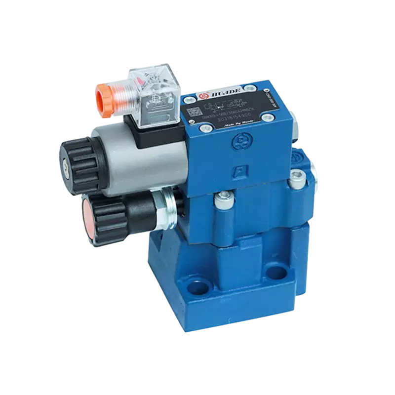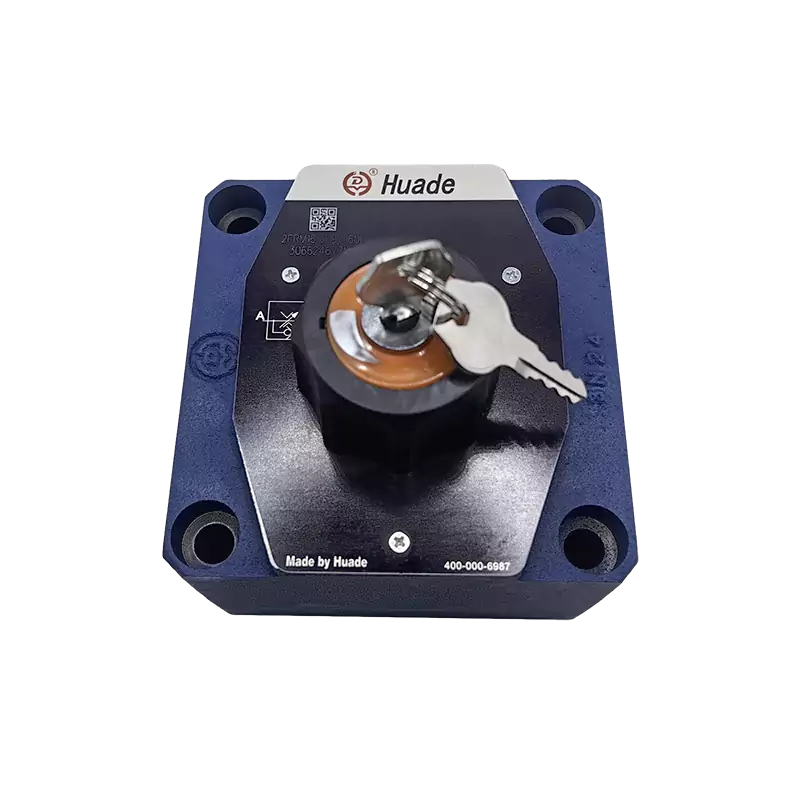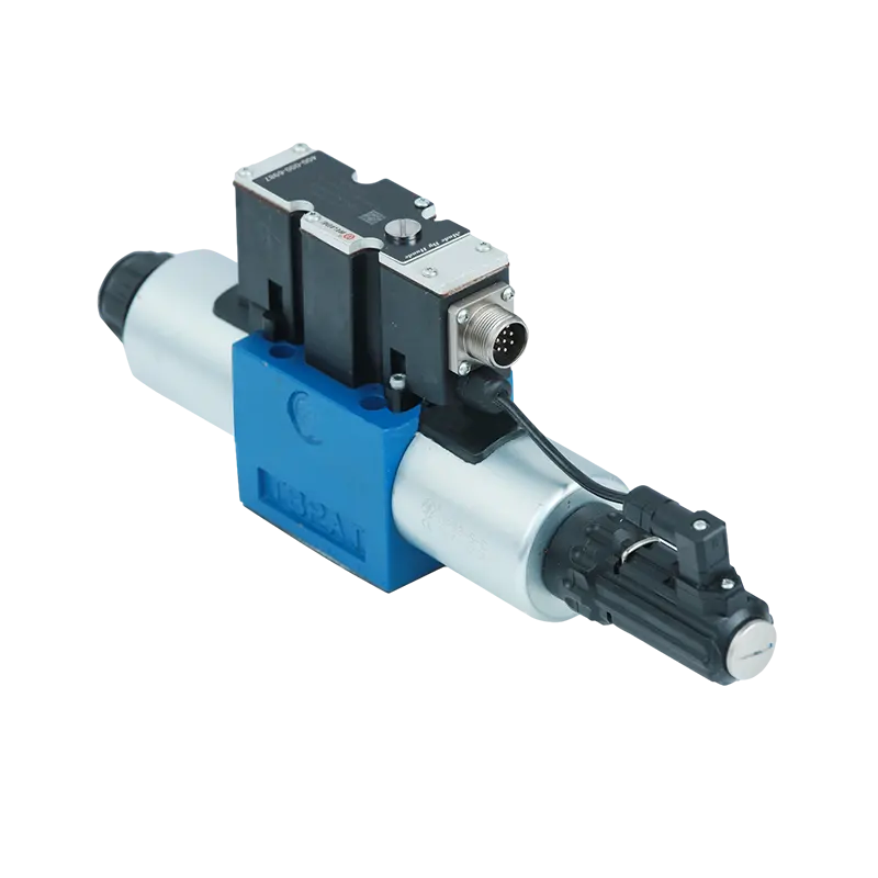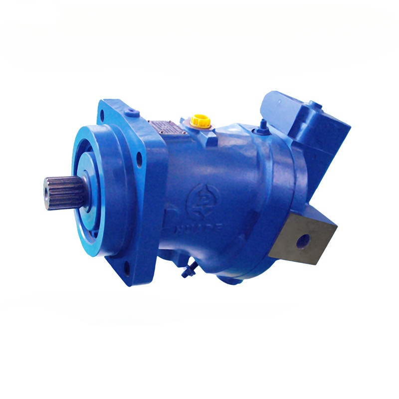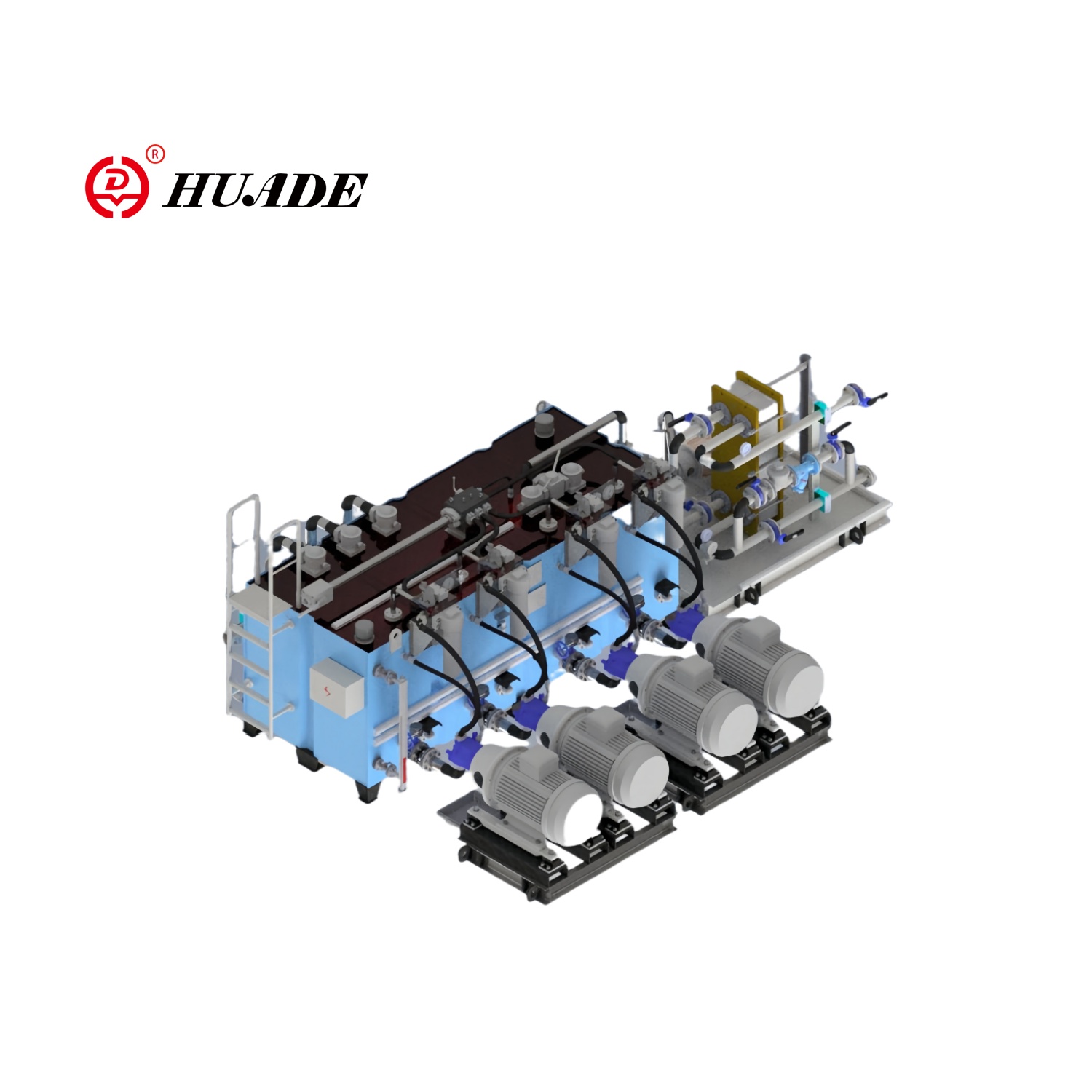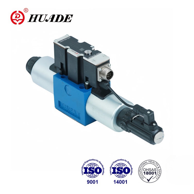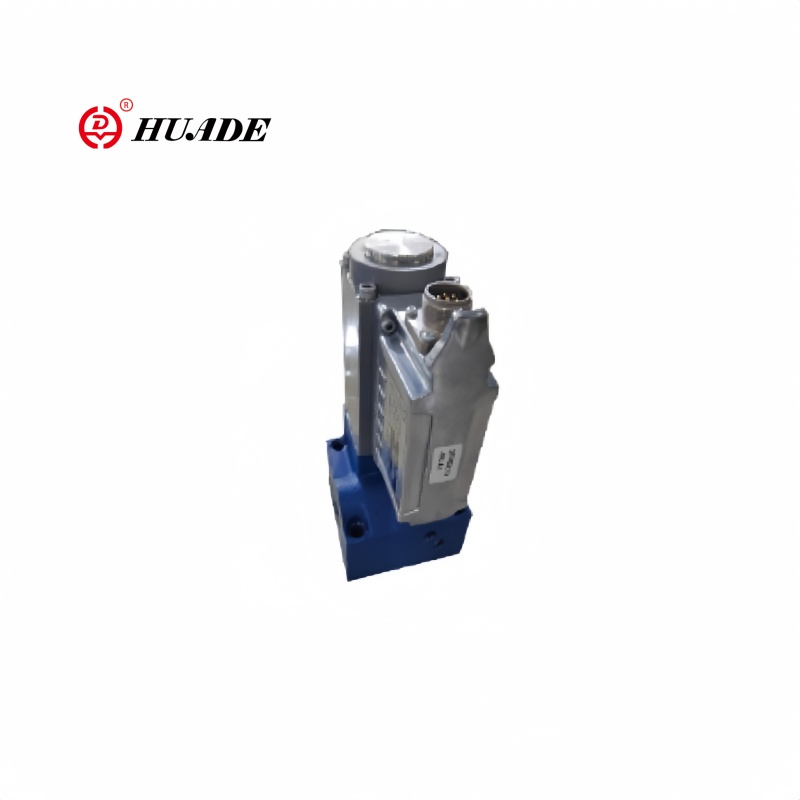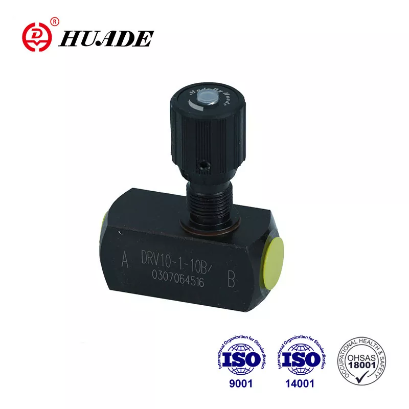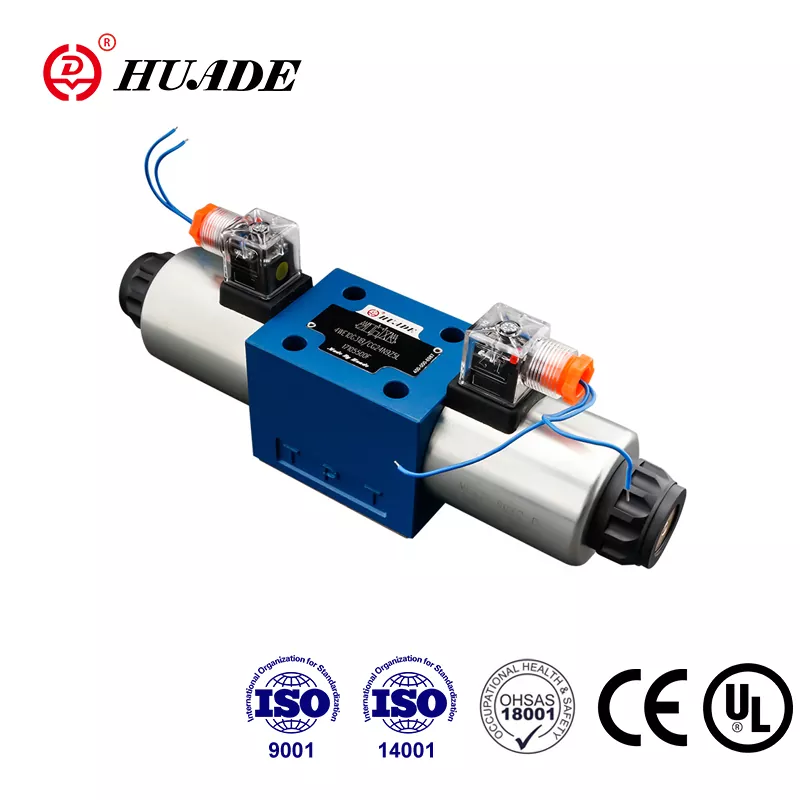
These valves are everywhere around us. You'll find them in excavators digging foundations, forklifts moving boxes in warehouses, and even in airplane control systems. Without these valves, heavy machines would be impossible to control.
How Do These Valves Work?
The Main Parts
Every hydraulic directional control valve has three key parts that work together:
1. Valve Body
The valve body is like the house where everything happens. It's usually made from strong materials like steel or aluminum. Inside, there are carefully drilled holes called ports. These ports have special names:
- P port: Where pressurized fluid comes in
- T port: Where fluid returns to the tank
- A and B ports: Where fluid goes to move cylinders or motors
2. Control Element
This is the moving part that actually directs the fluid. There are two main types:
Spool: A round, sliding piece that looks like a pencil with wider sections. As it slides back and forth, it opens and closes different pathways for the fluid.
Poppet: A cone-shaped piece that works like a cork in a bottle. It seals very tightly when closed but can open to let fluid through.
3. Actuator
This is what moves the control element. Common types include:
- Springs that push the valve back to a safe position
- Solenoids (electric magnets) that move when powered
- Manual levers for hand operation
- Pilot controls that use the system's own pressure
How Fluid Flows
Let's use a simple example with a hydraulic cylinder:
Neutral Position: When the valve is in the middle position, the cylinder stays put. Depending on the valve design, fluid might be blocked or allowed to return to the tank.
Extend Position: The valve connects the pressure port (P) to port A, sending fluid to extend the cylinder. At the same time, fluid from the other side of the cylinder flows back through port B to the tank (T).
Retract Position: Now the valve switches. Pressure goes to port B to retract the cylinder, while fluid returns from port A to the tank.
Types of Hydraulic Directional Control Valves
By Internal Design
Spool Valves
These are the most common type. The spool slides inside the valve body to create different flow paths.
Good points:
- Can handle complex operations with multiple positions
- Low resistance to fluid flow
- Versatile and widely used
Not so good:
- Small gaps allow some fluid to leak internally
- Can get stuck if the fluid is dirty
Poppet Valves
These use cone or ball-shaped elements that seal tightly against a seat.
Good points:
- Almost no internal leakage
- Work well with dirty fluid
- Great for holding heavy loads
Not so good:
- Limited to simple on/off functions
- Need more force to operate
By How They're Operated
Manual Valves: Operated by hand using levers, knobs, or buttons. Simple and reliable, but someone needs to be there to operate them.
Solenoid Valves: Use electric power to operate. These are perfect for automated systems and can be controlled by computers.
Pilot-Operated Valves: Use the system's own hydraulic pressure to move the main valve. This is like using a small valve to control a big valve - great for high-flow applications.
By Control Precision
On/Off Valves: Simple switches that are either fully open or fully closed. Like a light switch - it's either on or off.
Proportional Valves: These can open partially, like a dimmer switch for lights. The more you turn up the control signal, the more the valve opens. This gives you smooth speed control.
Servo Valves: The most precise type, used in applications that need extremely accurate control, like aircraft or precision manufacturing equipment.
Important Features and Specifications
Center Functions
For spool valves, what happens in the neutral (center) position is very important:
Closed Center: All ports are blocked. This locks the cylinder in place but makes the pump work harder.
Open Center: The pressure port connects to the tank. This saves energy by letting the pump run without pressure, but the cylinder might drift.
Tandem Center: A compromise that saves some energy while providing better load holding.
Key Performance Numbers
- Pressure Rating: How much pressure the valve can handle safely. Usually measured in PSI or bar.
- Flow Rate: How much fluid can pass through per minute. Usually measured in gallons per minute (GPM) or liters per minute.
- Response Time: How quickly the valve reacts to a control signal. Important for applications that need fast movements.
- Pressure Drop: How much pressure is lost as fluid flows through the valve. Lower is better for efficiency.
Valve Symbols and Standards
Engineers use special symbols to show valves in hydraulic diagrams. These symbols follow international standards (ISO 1219) so engineers worldwide can understand them.
A valve symbol shows:
- Boxes representing each position
- Arrows showing flow paths
- Lines with T-marks showing blocked paths
- Letters (P, T, A, B) marking the ports
- Symbols for springs and solenoids
For example, a "4/3 valve" means 4 ports and 3 positions.
Common Applications
Construction Equipment
Excavators use multiple directional control valves to operate the boom, arm, bucket, and tracks independently. Operators use joysticks that send signals to proportional valves for smooth control.
Manufacturing
Assembly lines use these valves to control robotic arms, presses, and conveyor systems. Solenoid-operated valves respond to computer commands for precise timing.
Agriculture
Modern tractors use proportional valve blocks to control implements like plows and harvesters. Some systems even integrate with GPS for automated field work.
Aerospace
Aircraft use extremely reliable servo valves for flight controls. These valves must work perfectly even in extreme conditions.
Top Manufacturers
Bosch Rexroth: Known for high-quality valves with advanced electronics and monitoring capabilities.
Parker Hannifin: Offers a wide range from basic industrial valves to specialized mobile equipment valves.
Eaton (Vickers): Famous for heavy-duty valves that last a long time in tough conditions.
Danfoss: Specializes in mobile hydraulics and energy-efficient systems.
HYDAC: Known for compact cartridge valves and custom manifold solutions.
Installation and Maintenance
Choosing the Right Valve
Consider these factors:
- Pressure and flow requirements: Match your system needs
- Control type: On/off for simple tasks, proportional for variable speed
- Environment: Choose seals and coatings suitable for your conditions
- Safety: Select center functions that provide safe operation
Common Problems and Solutions
Valve Won't Operate:
- Check electrical connections on solenoid valves
- Verify adequate hydraulic pressure for pilot-operated valves
- Look for mechanical obstructions
Slow or Erratic Operation:
- Clean or replace dirty hydraulic fluid
- Check for air in the system
- Inspect for worn valve components
External Leaks:
- Replace worn seals and gaskets
- Check mounting surface flatness
- Verify proper bolt torque
Best Practices
Installation:
- Keep everything clean during installation
- Use proper gaskets and sealing compounds
- Tighten bolts to specified torque values
Operation:
- Start with low pressure to check basic function
- Monitor system temperature and pressure
- Keep hydraulic fluid clean with proper filtration
Maintenance:
- Test valve operation regularly
- Change hydraulic fluid according to schedule
- Keep detailed maintenance records
Future Trends
The hydraulic valve industry continues to evolve:
Smart Valves: New valves include sensors and electronics that can report their condition and performance. This helps predict when maintenance is needed.
Energy Efficiency: Manufacturers are developing valves that waste less energy, helping reduce operating costs and environmental impact.
Integration: Valves are becoming more compact and integrated with other system components, reducing leak points and installation time.
Digital Control: More valves are designed to work with digital control systems and Internet of Things (IoT) networks.
Hydraulic directional control valves are essential components that make modern machinery possible. From simple on/off valves to sophisticated servo systems, these devices convert electrical or mechanical signals into controlled hydraulic power.
Understanding how these valves work, their different types, and how to select and maintain them is crucial for anyone working with hydraulic systems. As technology advances, these valves are becoming smarter, more efficient, and more integrated with digital control systems.
Whether you're operating heavy equipment, designing automation systems, or maintaining hydraulic machinery, knowledge of directional control valves will help you work more effectively and safely.
By choosing the right valve for your application and maintaining it properly, you can ensure reliable operation and long service life. The key is understanding your system requirements and matching them with the appropriate valve technology.
Remember, when in doubt, consult with hydraulic system experts or valve manufacturers. They can provide specific guidance for your unique application needs and help ensure optimal system performance.


