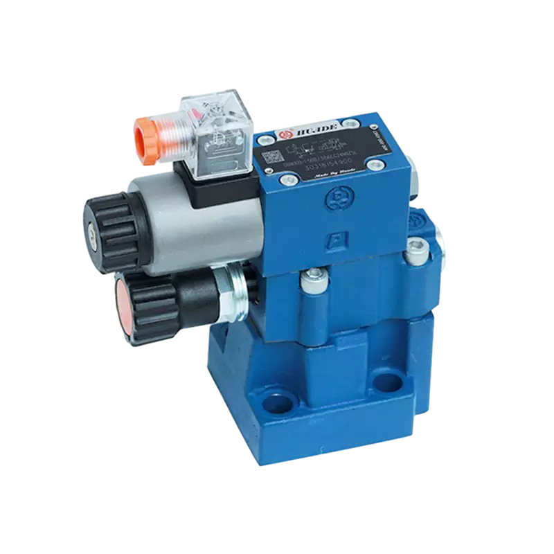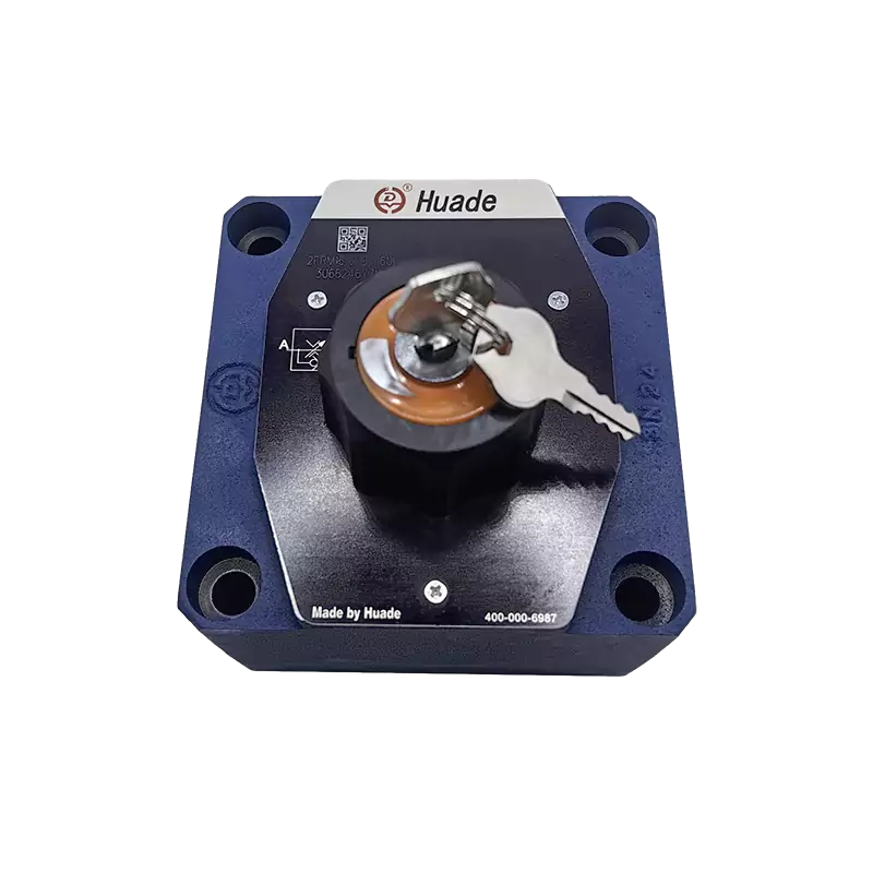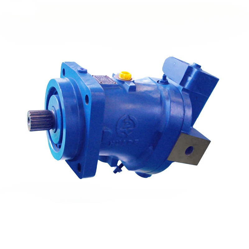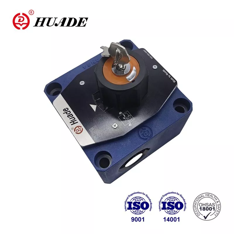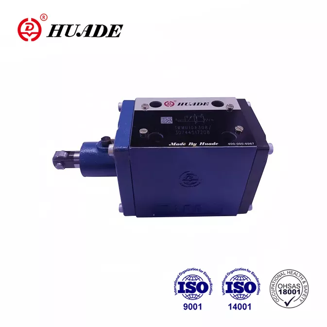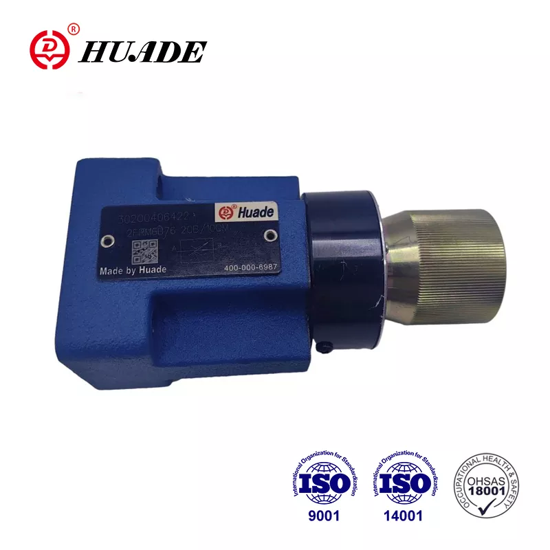
What is a Hydraulic Flow Control Valve?
A hydraulic flow control valve is like a traffic controller for fluid in hydraulic systems. Just as a traffic light controls how many cars pass through an intersection, these valves control how much hydraulic fluid flows through your system.
Simply put, hydraulic flow control valves regulate the speed of hydraulic motors and cylinders by controlling the amount of fluid that reaches them. More fluid means faster movement, less fluid means slower movement.
Why Are Flow Control Valves So Important?
Think of hydraulic fluid as the "blood" of a hydraulic system. Without proper flow control, your system would be like a person with uncontrolled blood pressure - either too fast and dangerous, or too slow and ineffective.
Here's what flow control valves do for your system:
How Do Hydraulic Flow Control Valves Work?
The basic principle is surprisingly simple. These valves work by creating a variable opening that fluid must pass through.
Imagine trying to fill a bucket with water. If you open the faucet just a little, water flows slowly. Open it wide, and water rushes out fast. Flow control valves work the same way - they adjust their opening size to control fluid flow rate.
The key factors that affect flow are:
- Opening size - Bigger opening = more flow
- Pressure difference - Higher pressure = faster flow (in basic valves)
- Fluid thickness - Thicker fluid = slower flow
Main Types of Hydraulic Flow Control Valves
1. Simple Flow Control Valves
Needle Valves
- Perfect for precise, small adjustments
- Like using a dropper instead of a fire hose
- Great for calibration and fine-tuning
- Downside: Flow changes when pressure changes
Throttle Valves
- Good for basic speed control
- Easy to adjust manually
- Common in simple systems
- Not very precise under varying loads
Ball Valves
- Mainly for on/off control
- Very durable and reliable
- Limited precision for speed control
- Great for isolating sections
2. Advanced Flow Control Valves
Pressure-Compensated Valves
The "smart" valves of hydraulic systems. Keep flow steady even when pressure changes.
Technical Details:
- Built-in pilot valve automatically adjusts main orifice size based on pressure differential
- Compensation Range: Typically maintains ±5% flow accuracy across 50-350 bar pressure range
- Internal Components: Spring-loaded compensator spool, adjustable throttling orifice, and pressure sensing ports
More expensive but much more reliable. Perfect for precision work.
Meter-In vs Meter-Out Valves
Limitation: Can cause cavitation with overrunning loads
Best for: Positive loads, vertical cylinders extending downward
Advantage: Creates backpressure to prevent cavitation
Best for: Overrunning loads, vertical cylinders retracting
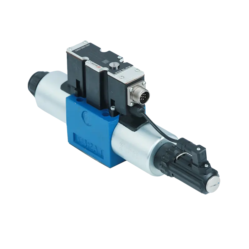
Proportional Flow Control Valves
Controlled electronically for super-precise adjustment.
- Control Method: PWM (Pulse Width Modulation) signals from electronic amplifier
- Feedback System: Closed-loop control with flow sensors or position feedback
- Response Time: Typically 10-50 milliseconds for step changes
- Signal Range: Standard 4-20mA or 0-10V control signals
- Amplifier Features: Current dithering to prevent valve sticking, ramp functions for smooth starts
Can be programmed and automated. Expensive but offer the best control. Common in modern CNC machines and robots.
Advanced Technical Concepts
Pressure Compensation Deep Dive
Pressure-compensated valves use a two-stage design:
- Primary Stage: Adjustable throttling orifice (user-controlled)
- Secondary Stage: Automatic compensator spool responds to pressure differential
Working Principle:
- Compensator maintains constant pressure drop (typically 7-10 bar) across the primary orifice
- When downstream pressure increases, compensator opens more to maintain flow
- When upstream pressure drops, compensator restricts to prevent flow increase
- Result: Consistent flow regardless of load changes
Proportional Valve Control Systems
Electronic Control Chain:
- Command Signal: 4-20mA or ±10V from PLC/controller
- Amplifier Processing: Converts signal to proper current/PWM
- Solenoid Response: Proportional solenoid creates force proportional to current
- Valve Response: Spool position directly relates to solenoid force
- Flow Output: Precise flow control with minimal hysteresis
Advanced Features:
Flow Divider Technology
Spool-Type Flow Dividers:
- Use synchronized spools to split flow
- Accuracy: ±5% flow division under normal conditions
- Pressure Sensitivity: Performance degrades with large pressure differences
- Applications: Suitable for similar load applications
Gear-Type Flow Dividers:
- Use precision gear sets for flow division
- Accuracy: ±2% flow division regardless of pressure differences
- Self-Compensating: Automatically adjusts for viscosity changes
- Applications: Critical synchronization (aircraft controls, heavy lifting)
Applications
Construction Equipment
- Excavators: Smooth arm and bucket movements
- Cranes: Precise lifting and positioning
- Bulldozers: Controlled blade adjustments
Manufacturing
- Injection molding machines: Perfect part formation
- CNC machines: Precise cutting speeds
- Assembly lines: Synchronized movements
Agriculture
- Harvesters: Coordinated cutting and collection
- Tractors: Implement control
- Irrigation systems: Water flow management
Other Applications
- Power plant turbines
- Water treatment facilities
- Oil and gas operations
- Mining equipment
How to Choose the Right Flow Control Valve
Selecting the right valve is like choosing the right tool for a job. Consider these factors:
1. System Requirements
- What pressure does your system operate at?
- How much flow do you need?
- What type of fluid are you using?
Technical Specifications Guide
| Application | Recommended Valve Type | Flow Rate | Max Pressure | Connection Size | Control Method |
|---|---|---|---|---|---|
| Small CNC Machine | Needle Valve | 2-8 L/min | 210 bar | 1/4" NPT | Manual |
| Injection Molding | Pressure-Compensated | 15-50 L/min | 350 bar | 1/2" SAE | Manual/Electric |
| Excavator Arm | Proportional | 80-200 L/min | 420 bar | 3/4" SAE | Electronic (PWM) |
| Hydraulic Press | Meter-Out | 25-100 L/min | 700 bar | 1" SAE | Pilot-Operated |
| Mobile Crane | Priority Valve | 120-300 L/min | 350 bar | 1" SAE | Load-Sensing |
2. Precision Needs
3. Environment
- Temperature Range: Standard valves work from -20°C to 80°C
- Extreme Conditions: Special seals needed for -40°C to 120°C
- Corrosive Fluids: Stainless steel or special coatings required
- High Vibration: Lock-wire adjustments or electronic control recommended
4. Budget Considerations
Common Problems and Solutions
Problem: Inconsistent Speed
Symptoms: Actuator speeds up and slows down randomly
Causes: Dirty fluid, worn valve parts, wrong valve type
Solution: Clean or replace fluid, service valve, upgrade to pressure-compensated valve
Problem: Overheating
Symptoms: System gets too hot, reduced performance
Causes: Internal leakage, wrong valve settings
Solution: Replace seals, adjust valve settings, check for proper valve sizing
Problem: Cavitation in Flow Control Systems
Symptoms: Loud noise, vibration, milky fluid, component damage
Technical Explanation: When fluid velocity exceeds critical limits, pressure drops below vapor pressure
Causes:
- Meter-in valves with overrunning loads
- Undersized valve orifices
- High fluid temperatures reducing vapor pressure
Solution:
- Switch to meter-out configuration
- Install anti-cavitation valves
- Increase orifice size or use multiple parallel valves
Critical Formula: Ensure flow velocity < 6 m/s in suction lines
Problem: Flow Control Valve Instability
Symptoms: Hunting, oscillation, unstable actuator movement
Technical Causes:
- Insufficient damping in proportional valve control loop
- Resonant frequency matching system natural frequency
- Gain settings too high in electronic amplifier
Solution:
- Adjust PID parameters (reduce proportional gain, increase damping)
- Add accumulator for system compliance
- Install flow restrictors in pilot lines
- Use valves with higher frequency response (servo valves)
Maintenance Tips for Long Life
Monthly Checks
- Look for external leaks around fittings
- Check fluid levels and color
- Listen for unusual noises
- Feel for excessive vibration
Quarterly Service
- Replace hydraulic filters
- Test fluid quality
- Check valve calibration
- Inspect seals and connections
Annual Maintenance
- Complete valve overhaul if needed
- Replace wear parts
- Update system documentation
- Train operators on proper use
The Future of Flow Control Valves
Technology is making these valves smarter and more efficient:
Key Takeaways
- Hydraulic flow control valves are speed controllers for hydraulic systems
- Different types serve different needs - from simple manual valves to advanced electronic ones
- Proper selection saves money and improves system performance
- Regular maintenance prevents expensive breakdowns
- New technology is making valves smarter and more efficient
Conclusion
Understanding hydraulic flow control valves doesn't have to be complicated. These vital components are simply the speed controllers of the hydraulic world, making sure everything moves at the right pace for safety, precision, and efficiency.
Whether you're operating heavy equipment, running a factory, or maintaining hydraulic systems, knowing how these valves work helps you make better decisions about equipment selection, maintenance, and troubleshooting.
Remember: the right flow control valve, properly maintained, is an investment that pays dividends in system reliability, energy savings, and operational safety. Choose wisely, maintain regularly, and your hydraulic system will serve you well for years to come.


