When people search for information about the Directional Control Valve WE 5 for Rexroth, they usually want to understand what this valve does, how it works, and whether it fits their needs. The WE 5 designation refers to a specific size category in Rexroth's valve lineup, but the story is more interesting than just one valve model.
What Is the Directional Control Valve WE 5
The original WE 5 from Rexroth was a directional control valve built to the NG5 size standard. These valves controlled hydraulic fluid flow in systems that needed moderate pressure and flow rates. The traditional WE 5 could handle pressures up to 250 bar and flow rates between 14 and 20 liters per minute. For many years, this performance level worked well for smaller hydraulic systems like compact machinery and light industrial equipment.
However, modern industrial applications demand more power and higher flow rates. This is where the evolution of the Directional Control Valve WE 5 becomes important. Rexroth developed the 5X series, which includes the 5-.WE 10 models. These newer valves maintain the design philosophy of the original WE 5 but scale up to NG10 size. The result is a valve that can handle up to 160 liters per minute at pressures reaching 420 bar. When engineers today search for a Directional Control Valve WE 5, they often end up choosing these NG10 models because they meet current performance requirements.
The Directional Control Valve WE 5 family follows international standards like ISO 4401-05 and NFPA D05. This standardization means the valves can mount on standard subplates and replace similar valves from other manufacturers without redesigning the entire system.
How the Valve Works Inside
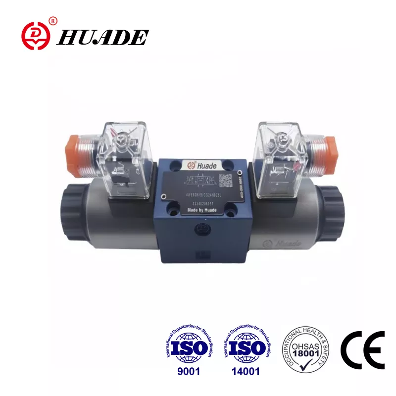
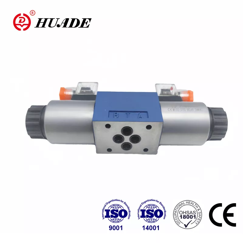
The basic structure of a Directional Control Valve WE 5 is straightforward. Inside the valve body sits a sliding spool that moves back and forth to connect different ports. When the spool shifts position, it changes which ports connect to each other. For example, the spool might connect port P (pressure) to port A while connecting port B to port T (tank). When the spool moves the other direction, it reverses these connections.
What makes the Directional Control Valve WE 5 move this spool? The answer is an electromagnetic solenoid. Rexroth uses what they call a "wet" solenoid design. The solenoid sits inside the hydraulic fluid rather than being sealed away from it. This might sound risky, but it actually provides better cooling and longer life. The hydraulic fluid carries away heat from the coil, allowing the solenoid to run continuously without overheating.
When you turn off power to the solenoid, springs inside the valve push the spool back to its center position. Different spring configurations create different behaviors. The standard setup uses return springs on both sides. Some versions use stronger springs to make the valve switch faster. Other versions eliminate springs entirely for special applications where the spool should stay in whatever position it moved to last.
Many Directional Control Valve WE 5 models include a manual override feature. This is a push button on top of the valve that lets someone move the spool by hand. During setup or troubleshooting, this manual control proves very useful. You can test the system without applying electrical power.
Performance Capabilities and Limits
The modern NG10 versions of the Directional Control Valve WE 5 system handle impressive performance numbers. Standard models work at 350 bar pressure, with special versions rated for 420 bar. Flow capacity reaches 160 liters per minute with DC voltage operation, or 120 liters per minute with AC voltage after rectification.
Temperature range spans from minus 30 degrees Celsius to plus 80 degrees Celsius. The valve works with hydraulic fluids ranging from very thin (2.8 millimeters squared per second) to quite thick (500 millimeters squared per second). This flexibility means one valve design serves many different applications.
However, high performance comes with some considerations. When fluid flows through the valve at maximum rates, hydraulic forces acting on the spool become substantial. These forces can cause instability or vibration. To manage this, Rexroth offers throttle cartridges that install in the ports. These cartridges restrict flow slightly, which reduces dynamic forces and smooths operation. The trade-off is higher pressure drop across the valve, but the improved stability is usually worth it.
Internal leakage is another characteristic of the Directional Control Valve WE 5 design. All spool valves leak some fluid past the spool because the spool needs clearance to move freely. This leakage increases gradually as the valve wears over thousands of cycles. For applications that need to hold loads in position for long periods, the Directional Control Valve WE 5 alone might not provide enough holding force. Adding external check valves or choosing a closed-center spool configuration helps solve this issue.
Electrical Control and Response Time
The electrical side of the Directional Control Valve WE 5 operates on standard industrial voltages. DC versions accept 12, 24, 110, or 220 volts, with 24 volts being most common. AC versions need a rectifier connector to convert alternating current to the direct current that the solenoid requires.
Power consumption ranges from 17 to 38 watts depending on the specific model. The valves are rated for 100 percent duty cycle, meaning they can stay energized continuously without damage. This continuous rating is important because many hydraulic systems hold a position for extended periods.
Response time varies based on several factors. Standard solenoids take between 65 and 150 milliseconds to turn on and between 48 and 104 milliseconds to turn off. These times might seem fast, but some applications need even quicker response. Rexroth offers pulse-width modulation cartridges that cut switching time in half. These PWM cartridges rapidly pulse the solenoid voltage in a controlled pattern that speeds up spool movement.
Another PWM option reduces energy consumption rather than improving speed. This energy-reduction cartridge drops the coil temperature by at least 30 degrees Celsius. Lower temperature extends valve life in hot environments or high-duty applications. Engineers need to choose between optimizing for speed or optimizing for thermal management. The Directional Control Valve WE 5 system provides options for both priorities.
When the solenoid switches off, the collapsing magnetic field generates a voltage spike. This spike can damage sensitive electronics connected to the same power supply. Standard K4 solenoids require external suppression diodes to clamp this voltage below 500 volts. The K72L solenoid version includes integrated protection, which simplifies wiring and ensures compliance with electrical safety standards.
Choosing the Right Spool Configuration
The spool inside a Directional Control Valve WE 5 determines what the valve does in each position. Most common are four-way, three-position spools. These spools have four ports (P, T, A, B) and three distinct positions (left, center, right).
The center position behavior is particularly important. An "E" spool closes all four ports in center position. This creates a closed center that locks the load in place and builds pressure at the pump. The E configuration provides maximum load holding but requires a relief valve to protect the pump from overpressure.
An "H" spool closes ports P, A, and B while connecting T in center position. This unloads the pump to tank, reducing energy waste when the valve is centered. The load stays locked because A and B are closed, but the holding force is not as strong as with an E spool.
A "J" spool closes P while connecting A, B, and T together in center position. This allows the load to float freely and lets thermal expansion escape to tank. The J configuration is useful for systems that need to move easily in neutral position or for preventing pressure buildup from temperature changes.
Choosing the wrong spool type creates problems. For example, using an H spool on a vertical lift application might let the load drift down slowly due to internal leakage. An E spool would hold better. On the other hand, using an E spool on a horizontal axis that needs to move freely would make the system feel stiff and waste energy. Understanding your application helps you select the right Directional Control Valve WE 5 configuration.
Installation and Maintenance Considerations
Installing a Directional Control Valve WE 5 requires attention to a few key points. The valve mounts on a subplate that must meet ISO 4401-05 standards. Rexroth subplates have specific part numbers and need to be ordered separately. Before installing the valve, make sure the subplate is clean and properly installed on the manifold or block.
Electrical connections use DIN EN 175301-803 standard connectors. The connector can be rotated 90 degrees to accommodate different wire routing needs. Some connectors include built-in rectifiers for AC operation, while others add LED indicators for visual confirmation of solenoid state.
Fluid cleanliness matters more than most people realize. The clearances inside the Directional Control Valve WE 5 measure only a few micrometers. Contamination particles can jam the spool, causing the valve to stick or fail to shift. Filtration to 25 micrometers or finer is strongly recommended. Regular filter maintenance prevents most valve problems.
The valve works with mineral-based hydraulic oils and several types of biodegradable fluids. Seal materials come in NBR (nitrile) for standard oils or FKM (Viton) for synthetic fluids and high temperatures. Make sure seal material matches the fluid in your system.
Maintenance is relatively simple. The solenoid coils are replaceable without removing the valve from the system. Check coil resistance periodically to detect degradation before failure occurs. If the valve starts to respond slowly or fails to shift, contamination is the most likely cause. Flushing the system and replacing filters usually solves the problem. Worn internal components can be replaced with genuine Rexroth spare parts, which are typically available for ten years after production.
Making the Purchase Decision
When you decide to buy a Directional Control Valve WE 5 or its modern NG10 equivalent, several factors influence the choice. First, verify your flow and pressure requirements. If you need less than 20 liters per minute at moderate pressure, a traditional NG5 size might suffice. For higher performance, the 5X series NG10 models are the current standard.
Second, consider the electrical voltage available in your facility. The 24-volt DC version is most common in industrial automation, while 110 or 220-volt options suit different regions and applications.
Third, evaluate whether you need special features like fast switching, energy reduction, or position monitoring. These options add cost but provide real benefits in demanding applications.
Price varies considerably based on specifications and supplier. Authorized distributors and industrial suppliers carry these valves, often with technical support to help with selection. Bulk purchases typically qualify for volume discounts. The official Rexroth catalog provides detailed specifications and ordering codes to ensure you get exactly the right valve.
Alternative suppliers offer compatible valves at lower prices, but compatibility and reliability can vary. For critical applications, genuine Rexroth valves provide better long-term value through consistent performance and parts availability.
Practical Applications and Success Factors
The Directional Control Valve WE 5 and its descendants find homes in countless applications. Injection molding machines use them to control mold clamps and ejectors. Robotic systems rely on them for precise motion control. Forklifts depend on them for steering and lift functions. Metal forming presses, machine tools, and material handling equipment all incorporate these valves.
Success with any Directional Control Valve WE 5 installation depends on matching the valve to the application requirements. High-flow applications need throttle cartridges to maintain stability. High-temperature environments benefit from energy-reduction solenoids. Load-holding applications require closed-center spools and possibly external check valves.
The electrical system must provide proper voltage and include protection against voltage spikes. Hydraulic system design should account for pressure drops through the valve and provide adequate filtration.
Regular maintenance extends valve life and prevents unexpected downtime. Simple practices like monitoring filter condition, checking for external leakage, and testing solenoid response keep the system running reliably.
The evolution from the original WE 5 to the modern 5X series demonstrates how industrial hydraulic components advance to meet changing needs. Understanding both the heritage and current capabilities helps engineers make informed decisions about which Directional Control Valve WE 5 variant best serves their application. With proper selection, installation, and maintenance, these valves deliver years of dependable service in demanding industrial environments.